


POWER ELECTRONICS
DB SERIES
INSTALLATION OF DYNAMIC BRAKING UNIT
23
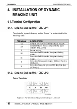
4.5.
Operation Modes for Dynamic Braking Unit –
GROUP 2
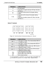
4.5.1.
‘Single’ Operation Mode
This operation mode refers to the connection of only one dynamic
braking unit to the drive.
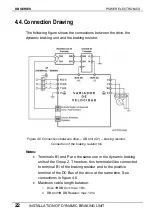
In order to obtain information about the wiring between dynamic
braking unit and drive, see figure 4.5.
Note:
When only one dynamic braking unit is connected to the drive,
this one should be configured as ‘Master’ (factory setting). To get
additional information, see section “4.5.2. ‘Master / Slave’ Operation
Mode”.
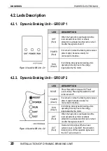
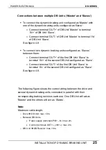
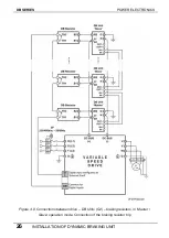
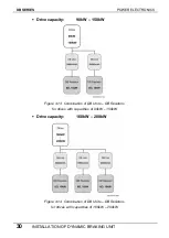
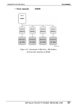
4.5.2.
‘Master / Slave’ Operation Mode
When two or more dynamic braking units are connected to the drive in
parallel.
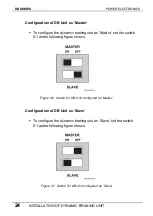
In this case, one DB Unit should be configured as ‘Master’ and the
others should be configured as ‘Slave’ by using the switch S1. In order
to access to it, it is necessary to remove the front cover of the DB Unit.
This switch is located in the centre of the electronic board (PCB) which
is visible.
Summary of Contents for SDRIVE DB Series
Page 1: ...DB Series SDRIVE S D Y N A M I C B R A K I N G dynamic braking unit Getting Started Manual...
Page 2: ...dynamic braking unit Getting Started Manual Edition October 2007 VFDF01AI Rev A...
Page 3: ...DB SERIES POWER ELECTRONICS 2...
Page 5: ...DB SERIES POWER ELECTRONICS 4...
Page 7: ...DB SERIES POWER ELECTRONICS 6 INDEX...
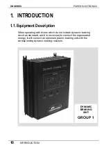
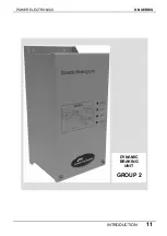
Page 12: ...POWER ELECTRONICS DB SERIES INTRODUCTION 11 DYNAMIC BRAKING UNIT GROUP 2...
Page 35: ...DB SERIES POWER ELECTRONICS 34 DYNAMIC BRAKING RESISTOR...
Page 36: ...POWER ELECTRONICS DB SERIES DYNAMIC BRAKING RESISTOR 35...
Page 38: ...www power electronics com...


