POWER ELECTRONICS
DB SERIES
INSTALLATION OF DYNAMIC BRAKING UNIT
27
4.6.
Combination of DB Units according to Drive
Capacity
4.6.1.
Combination of DB Units – GROUP 1
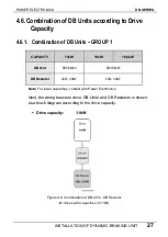
CAPACITY
11kW
15kW
18,5kW
DBSD4030 DBSD4045
DB Unit
30
Ω
, 2,5kW
20
Ω
, 3,5kW
DB Resistor
Note:
For lower capacities, contact with Power Electronics.
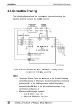
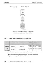
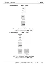
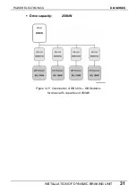
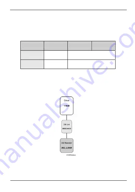
Next, the wiring between drive, DB Units and DB Resistors is shown
as a block diagram according to the drive capacity.
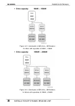
Drive capacity:
11kW
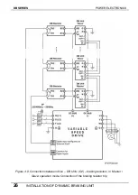
Figure 4.9 Combination of DB Unit – DB Resistor
for drives with capacities of 11kW
Summary of Contents for SDRIVE DB Series
Page 1: ...DB Series SDRIVE S D Y N A M I C B R A K I N G dynamic braking unit Getting Started Manual...
Page 2: ...dynamic braking unit Getting Started Manual Edition October 2007 VFDF01AI Rev A...
Page 3: ...DB SERIES POWER ELECTRONICS 2...
Page 5: ...DB SERIES POWER ELECTRONICS 4...
Page 7: ...DB SERIES POWER ELECTRONICS 6 INDEX...
Page 12: ...POWER ELECTRONICS DB SERIES INTRODUCTION 11 DYNAMIC BRAKING UNIT GROUP 2...
Page 35: ...DB SERIES POWER ELECTRONICS 34 DYNAMIC BRAKING RESISTOR...
Page 36: ...POWER ELECTRONICS DB SERIES DYNAMIC BRAKING RESISTOR 35...
Page 38: ...www power electronics com...

