DB SERIES
POWER ELECTRONICS
5.
DYNAMIC BRAKING RESISTOR
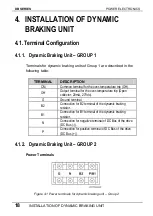
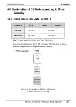
5.1.
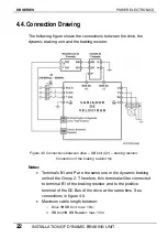
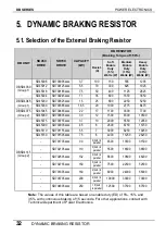
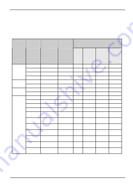
Selection of the External Braking Resistor
DB RESISTOR
(Braking Torque of 150%)
SD450
SD700
CAPACITY
Soft
Medium
Heavy
DB UNIT
DRIVE
DRIVE
(kW)
Enable
Enable
Enable
Resist.
Duty
Duty
Duty
(
Ω
)
(5%)
(15%)
(35%)
Watts (W) Watts (W)
Watts (W)
SD45008 SD700095xxxx
3,7 100
150 555 1295
SD45012 SD700125xxxx
5,5 70
300 825 1925
DBSD4030
SD45016 SD700185xxxx
7,5 50
400 1125 2625
(Group 1)
SD45024 SD700245xxxx
11 35
600 1650
3850
SD45030 SD700325xxxx
15 25
800 2250
5250
DBSD4045
(Group 1)
SD45039 SD700385xxxx
18,5 20
1000 2775 6475
SD45045 SD700485xxxx
22 17
1100
3300
7700
DBSD4075
(Group 2)
SD45060 SD700605xxxx
30 12
1500
4500
10500
SD45075 SD700755xxxx
37 10
2000
5550
12950
SD45090 SD700905xxxx
45 8
2500
6750
15750
SD45110 SD701155xxxx
55 7
3000
8250
19250
SD45150 SD701505xxxx
75 6
4000
11250
26250
3 (2x6) in
parallel
- SD701705xxxx
90
4500 13500 31500
3 (2x6) in
parallel
- SD702105xxxx
110
5500 16500 38500
- SD702505xxxx
132
3 (2x6) in
parallel
6600 19800 46200
DBSD4145
(Group 2)
3 (2x6) in
parallel
- SD702755xxxx
150
7500 22500 52500
2 (3x6) in
parallel
- SD703305xxxx
160
8000 24000 56000
2 (3x6) in
parallel
- SD703705xxxx
200
10000 30000 70000
1,5 (4x6)
in parallel
- SD704605xxxx
250
12500 37500 87500
Note:
The values of this table are based on enable duty (ED) of 5%, 15% and
35%, with continuous braking of 15 seconds. For other applications, contact with
Technical Department of Power Electronics.
32
DYNAMIC BRAKING RESISTOR
Summary of Contents for SDRIVE DB Series
Page 1: ...DB Series SDRIVE S D Y N A M I C B R A K I N G dynamic braking unit Getting Started Manual...
Page 2: ...dynamic braking unit Getting Started Manual Edition October 2007 VFDF01AI Rev A...
Page 3: ...DB SERIES POWER ELECTRONICS 2...
Page 5: ...DB SERIES POWER ELECTRONICS 4...
Page 7: ...DB SERIES POWER ELECTRONICS 6 INDEX...
Page 12: ...POWER ELECTRONICS DB SERIES INTRODUCTION 11 DYNAMIC BRAKING UNIT GROUP 2...
Page 35: ...DB SERIES POWER ELECTRONICS 34 DYNAMIC BRAKING RESISTOR...
Page 36: ...POWER ELECTRONICS DB SERIES DYNAMIC BRAKING RESISTOR 35...
Page 38: ...www power electronics com...


