background image

V 1.45

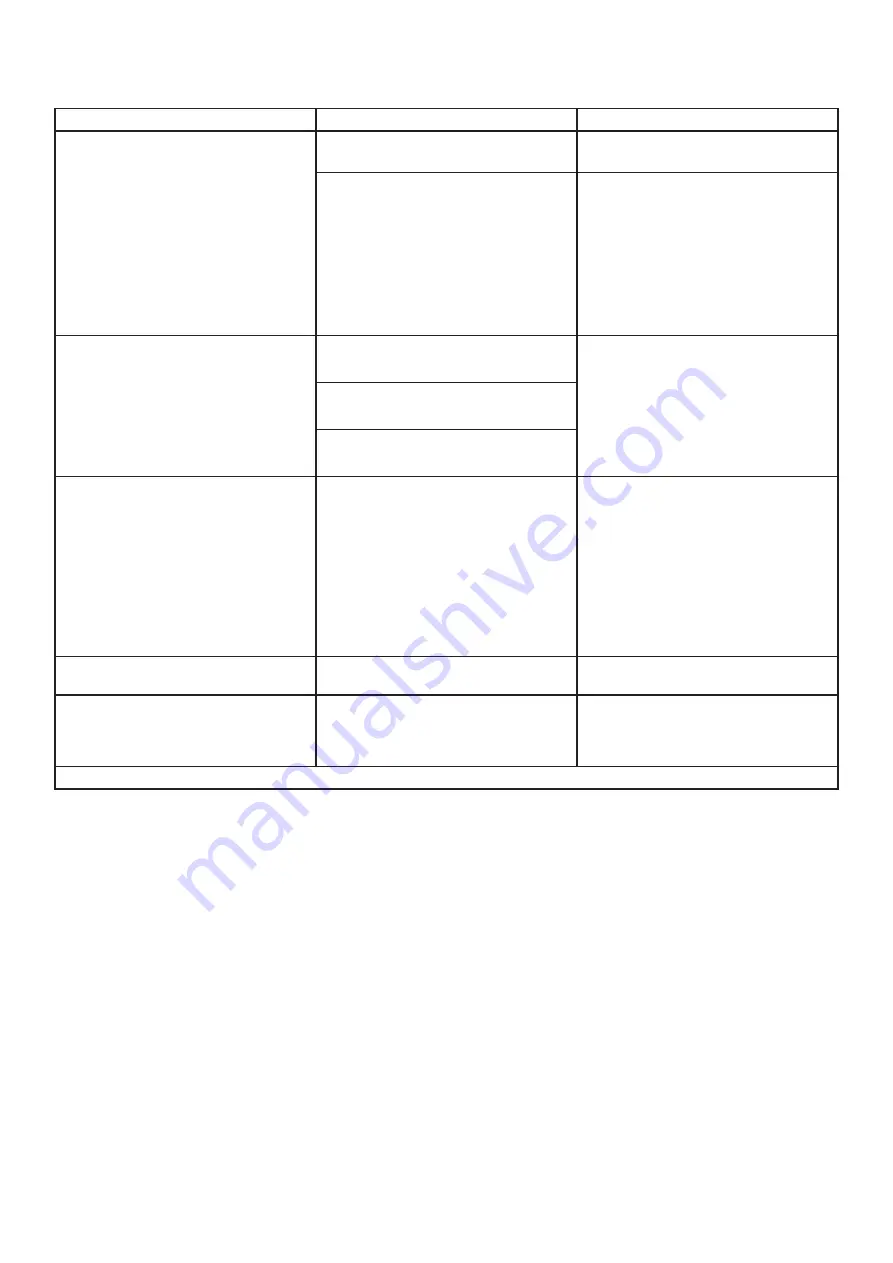
TROUBLE SHOOTING

Problems

Possible causes

Suggested solutions

Tool runs at normal speed but loses 
under load.

Motor parts worn.

Have a qualified technician replace 
worn parts.

Cam clutch worn or sticking due to 
lack of lubricant.

1.


Lubricate clutch housing.

2.


Check for excess clutch oil.

3.


Overfilling can cause drag on high 
speed clutch parts, ie, a typical oiled/
lubricated wrench requires ½ Ounce of 
oil.

Grease lubricated note: 

Heat usually indicates insufficient grease 
in chamber. Severe operating conditions 
may require more frequent lubrication.

Tool runs slowly. Air flows slightly from 
exhaust.

Motor parts jammed with dirt 
particles.

1.


Check air inlet filter for blockage.

2.


Pour air tool lubricating oil into air inlet 
as per instructions.

3.


Operate tool in short bursts quickly 
reversing rotation back and forth where 
applicable.

4.


Repeat above as needed.

 If this fails 

return to service center.

Power regulator in closed  position.

Air flow blocked by dirt.

Tools will not run. 

Air flows freely from 

exhaust.

O-rings throttle valve dislodged from 
seat inlet valve.

1.


Pour air tool lubricating oil into air inlet 
as per instructions.

2.


Operate tool in short bursts of forward 
and / or reverse rotation where 
applicable.

3.


Tap motor housing gently with plastic 
mallet.

4.


Disconnect supply.

 Free motor by 

rotating drive shank manually where 
applicable 

5.


If tool remains jammed return to service 
centre.

Tool will not shut off.

O-rings throttle valve dislodged from 
seat inlet valve.

Have a qualified technician replace the 
O-ring.

Loss of power or erratic performance.

Excessive drain on the air line. 
Moisture or restriction in the air 
pipe.

 Incorrect size or type of hose 

connectors.

Check the air supply.

 If tool is not 

corrected to a 1/4" line, connect it 
properly.

Note: Repairs should be carried out by a qualified person

For any technical questions, please call 1-800-665-8685

7

0450071

Summary of Contents for 0450071

Page 1: ...V 1 45 Professional HVLP Paint Gun 0450071 OWNER S MANUAL Read and understand all instructions before use Retain this manual for future reference ...

Page 2: ...ed equipment When not in use tools must be stored in a dry location to prevent rust Always lock up tools and keep them out of reach of children PERSONAL SAFETY 1 Use eye and breathing protection Always wear ANSI approved impact safety goggles which must provide both frontal and side protection Protect your hands with suitable gloves Wear an ANSI approved dust mask or respirator when working around...

Page 3: ...d or replaced by a qualified technician 2 When servicing use only identical replacement parts Only use accessories intended for use with this tool Replace damaged parts immediately AIR SOURCE 1 Disconnect air supply Disconnect tools from air pressure source when not in use before cleaning servicing or changing a piece or accessory After disconnecting discharge any residual air pressure 2 Do not us...

Page 4: ... fingers seek medical attention as soon as possible 2 Do not smoke during use Nicotine reduces the blood flow to the hands and fingers increasing the risk of vibration related injury 3 Wear suitable gloves to reduce the vibration effects on the user 4 Use tools with the lowest amount of vibration when there is a choice between different processes 5 Do not use for extended periods Take frequent bre...

Page 5: ...air pressure hose and discharge any residual pressure inside the tool before changing accessories or making any adjustments to the tool Failure to do so could result in severe injury tool or property damage OPERATION 1 Suggested air pressure is 43 PSI 2 Recommended paint viscosity differs according to paint properties and painting conditions 3 Use the lowest possible fluid output that produces an ...

Page 6: ...l be left to sit for a few hours or more before its next use it must be cleaned to prevent the paint from drying inside the ducts 1 After you have finished painting pour the remaining paint into another container and then clean paint passage and air cap Spray a small amount of thinner to clean paint passages Incomplete cleaning will cause adverse pattern shapes and particles to appear on your work...

Page 7: ...4 Repeat above as needed If this fails return to service center Power regulator in closed position Air flow blocked by dirt Tools will not run Air flows freely from exhaust O rings throttle valve dislodged from seat inlet valve 1 Pour air tool lubricating oil into air inlet as per instructions 2 Operate tool in short bursts of forward and or reverse rotation where applicable 3 Tap motor housing ge...

Page 8: ...e hole of the head part Uneven pattern Material builds up on the outside of fluid nozzle tip or center hole or partially clogged nozzle orifice Loose fluid nozzle Clean the head and nozzle Make sure that the centering between the two is precise Check the tip of the pin is not ruined Replace the nozzle and the head The center of the pattern is too narrow Atomization of air pressure is too high Mate...

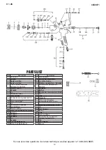
Page 9: ...e 13H Screw 14 Washer 14A Spray Regulating Screw 14B Spray Regulating Nut For any technical questions please call 1 800 665 8685 9 Description 14C O Ring 15 Control Knob 15A Countersunk Screw 16 Paint Needle Complete 17 Spring for Paint Needle 18 Washer 19 Housing 20 Fluid Control Knob 21 Screw 22 Pin 23 Trigger 24 Air Connector Piece 1 4 BSP 32 Material Sleeve Filters 34 Screw 35 O Ring 36 Nut 37...

Page 10: ...tainer Cover 1 14 Check Valve Bracket 1 15 Handle 1 16 Regulator Assembly 1 17 1 4 Dia Brass Ball 1 18 Air Connection 1 4 NPS 1 19 H Valve Spring 1 0450071 Description Qty 20 Air Connection 1 4 NPS 1 21 Adjusting Cap 1 22 Safety Valve Spring 1 23 Air Gauge 15 PSI 1 24 Adjusting Spring 1 25 Safety Valve Body 1 26 Safety Valve Spring Screw 1 27 Safety Valve 10 PSI 1 28 Regulator Body 1 29 Gauge Lens...

Page 11: ...tion Qty 17 Spring 1 18 Diaphragm Retaining Nut 1 19 Pilot Valve Diaphragm Assembly 1 20 Diaphragm Assembly 1 21 Valve Seat Holder 1 22 Pilot Regulator Valve Assembly 1 23 Spring 1 24 Spring Expander 1 25 Body 1 26 Air Adjusting Valve 1 27 O Ring 1 28 Adjusting Screw 1 PARTS LIST Description Qty 29 Spring Kit 1 30 Valve Disc Assembly 1 31 Coupling 1 4 NPS M x 1 8 NPT M 1 32 Control Valve Assembly ...

Page 12: ...V 1 45 For any technical questions please call 1 800 665 8685 12 0450071 ...

Page 13: ... à Peinture Professionnel HVBP 0450071 MANUEL DU PROPRIÉTAIRE Vous devez lire et comprendre toutes les instructions avant d utiliser l appareil Conservez ce manuel afin de pouvoir le consulter plus tard V 1 45 ...

Page 14: ...e d un gaz ou de poussières inflammables Les outils mécaniques produisent des étincelles qui peuvent enflammer la poussière ou les fumées 3 Quand vous utilisez cet outil tenez les spectateurs les enfants et les visiteurs à une distance prudente Ne les laissez pas manipuler des outils ou des rallonges Aucune personne qui ne porte pas l équipement de protection approprié devrait être dans l aire de ...

Page 15: ...vant de mettre l outil en marche retirez les clés et les clavettes de réglage s il y a lieu Toute clé ou clavette qu on laisse attachée à une pièce rotative de l outil pose un risque de blessures corporelles 5 Évitez les démarrages accidentels Avant de raccorder l outil à sa source d air comprimé d alimentation assurez vous que le levier de la soupape à air l interrupteur est à sa position arrêt O...

Page 16: ... de 16 pi3 min pour fonctionner à son régime maximal LUBRIFICATION 1 Cet outil est différent de la majorité des outils pneumatiques dans le sens qu il n est pas recommandé de le lubrifier de façon typique Introduire de l huile pour outils pneumatiques dans cet outil pourrait se mélanger avec le produit à être pulvérisé et boucher le pistolet ce qui pourrait endommager l outil N utilisez pas cet ou...

Page 17: ...bon solvents trichloromethyl or trichloroethylene etc because they can trigger chemical reactions with some of the materials in the paint spray gun and create the risk of dangerous explosions 2 Make sure that all the paint and solvent products used are compatible by cross checking the respective product technical safety cards 3 Ground both the spray painting machine and the object to be painted in...

Page 18: ...o be painted 6 In order to obtain a uniform finish during painting keep the paint spray gun perpendicular and at a constant distance from the surface to be painted 7 Spray the paint in horizontal swatches If the finish is not adequate make sure that the pressure is not too low and that the paint spray gun is not being held too far from the surface to be painted Si vous avez des questions de nature...

Page 19: ...e trigger to clean the internal paint spray gun s passages from all traces of paint before disassembly 3 Unscrew and remove the paint spray gun s head submerge it in solvent and brush it clean Do not use metal objects for cleaning 4 After removing the needle unscrew the nozzle using the correct wrench insert it in solvent and brush it clean Wash the inside of the paint spray gun and brush it clean...

Page 20: ...l par petits coups en changeant rapidement la rotation dans un sens puis dans l autre le cas échéant 4 Répétez la manoeuvre ci dessus selon le besoin Régulateur de puissance en position fermée Saleté qui bloque le débit d air L outil refuse de marcher L air sort librement de l échappement Moteur coincé à cause d une accumulation de matière 1 Versez de l huile lubrifiante pour outils pneumatiques d...

Page 21: ... dans la buse Nettoyez la tête et la buse Assurez vous que le centrage entre les deux est précis Assurez vous que la pointe de l aiguille n est pas abîmée Remplacez la buse et la tête Gicleur de liquide est deserré Reserrez le gicleur Le centre de la couche est trop mince La pression et la quantité d air sont excessives par rapport au débit de peinture Réduisez la quantité d air et augmentez le dé...

Page 22: ...éflon 13D Corps de soupape pneumatique 13E Joint PC 13F Soupape 13G Soupape 13H Vis 14 Rondelle 14A Vis de réglage de jet 14B Écrou de réglage de jet No Description 14C Joint torique 15 Bouton de commande 15A Vis à tête fraisée 16 Pointeau de peinture Complet 17 Ressort pour pointeau de peinture 18 Rondelle 19 Boîtier 20 Bouton de commande de fluide 21 Vis 22 Tige 23 Gâchette 24 Pièce de connecteu...

Page 23: ...ouvercle de récipient 1 14 Support de clapet de non retour 1 15 Poignée 1 16 Ensemble de régulateur 1 17 Bille en laiton 1 4 dia 1 18 Connexion pneumatique 1 4 NPS 1 19 H Ressort de soupape 1 No Description Qté 20 Connexion pneumatique 1 4 NPS 1 21 Couvercle de réglage 1 22 Ressort de soupape de sécurité 1 23 Manomètre à air 15 psi 1 24 Ressort de réglage 1 25 Corps de soupape de sécurité 1 26 Vis...

Page 24: ...t 1 18 Écrou de retenue de diaphragme 1 19 Ensemble de soupape pilote et de diaphragme 1 20 Ensemble de diaphragme 1 21 Support de siège de soupape 1 22 Ensemble de soupape de régulateur pilote 1 23 Ressort 1 24 Extension à ressort 1 25 Corps 1 26 Soupape de réglage pneumatique 1 27 Joint torique 1 28 Vis de réglage 1 PARTS LIST No Description Qté 29 Trousse de ressort 1 30 Ensemble de soupape et ...

Reviews: