Visit www.princessauto.com for more information
5
8533614
V 3.05
1/3 HP 2,900 GPH Sump Pump with Enclosed Float Switch
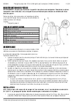
PARTS IDENTIFICATION
WARNING! Do not operate the device if any part is missing. Replace the missing part before operating.
Failure to do so could result in a malfunction and personal injury.
Remove the parts and accessories from the packaging and inspect for damage. Make sure that all items in the
parts list are included.
Contents:
• Sump Pump
IDENTIFICATION KEY
A
Carrying handle
B
Mains cable and plug
C
Hose adapter for pressure connection
D
Pump casing
E
Built-in float switch
F
Pump base
G
Automatic-Manual change-over switch
ASSEMBLY
When this manual refers to a part number, it refers to the
included Parts Identification section.
The pump comes preassembled. However, it must be
connected to a pipe system to expel the water.
1. Calculate the head from the pump outlet to the end of
the pipe. The total cannot exceed 27 feet (see Specifications).
2. Connect the pump to the pipe using a proper adapter. A sealant may be required when attaching to ABS,
PVC or a polyethylene pipe. A physical method of sealing the adapter to a galvanized steel pipe, such as a
hose clamp, may be acceptable. Any threaded connection should have a sealant applied.
3. Install a check valve in the discharge line to prevent the backflow of liquid into the basin. The check
valve should be a free-flow valve that will easily pass solids, such as sediment. Install the check valve
horizontally or at an angle of no more than 45° for the best performance. Do not install the check valve
vertically, because solids may settle in the valve and prevent it from opening on start-up.
a. When using a check valve, drill a 1/8 in. (3 mm) or 3/16 in. (5 mm) diameter relief hole in the
discharge pipe below the floor line between the pump discharge and the check valve. Otherwise, the
pump could air lock and will not pump water even though the pump will run.
INSTALLATION
NOTICE! This pump is intended to pump water only, with a maximum temperature of 35°C (95°C). Pumping
heated liquids will damage the pump mechanism.
1. The sump pump requires a basin at least 20 x 20 in. (50 x 50 cm) to provide enough room for the float
switch to move freely.
2. Install the sump pump so that the suction openings cannot be blocked by foreign bodies by placing the
pump on a firm, even base. Do not place the pump on clay, earth or gravel surfaces.
3. Submerge the pump at an angle into the water to prevent air pockets from forming on the underside that
would interfere with suction. Once the pump is submerged, it can be righted again.
Summary of Contents for 8533614
Page 8: ......


