background image

18

Power-Flo Pumps & Systems • 877-24PUMPS • www.powerflopumps.com

Maintenance

No lubrication or maintenance is required. 
Perform the following checks when  pump 
is removed from operation or when pump 
performance deteriorates:
a).   Inspect seal chamber for oil level 
 

and contamination.

b).  Inspect impeller, adjust cutter knife 
 

and blade.

c).  Inspect motor and bearings.
d).  Inspect lower seal for wear or leakage.

Servicing

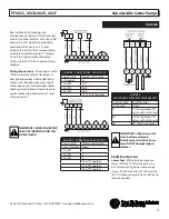
NOTE: Item numbers in ( ) refer to Figures 

6 & 7.

Seal Chamber Oil - 

Anytime the pump 

is removed from operation, the oil in the 

seal chamber should be checked visually 

for oil level and contamination.

To check oil, set unit on its side with pipe 

plug (23) downward, remove pipe plug 

(23) and drain oil from seal chamber. 

Make sure it is clean and clear, light 

amber in color and free from suspended 

particles. Milky white oil indicates the 

presence of water and lower seal should 

be inspected or replaced.

Oil Testing

•  Check oil for contamination using an 

  oil tester with a range to 30 Kilovolts 

  breakdown.
•  If oil is found to be clean and 

  uncontaminated (measuring above 

  15 KV. breakdown), refill seal chamber.
•  If oil is found to be dirty or 

  contaminated (or measures below 

  15 KV. breakdown), the pump must 

  be carefully inspected for leaks. 

After leak is repaired, dispose of old oil 

properly, and refill with new oil.

Oil Replacement: 

Seal Chamber -

 Drain all oil (if not already 

done so) from seal chamber and dispose 

of properly per Local and Environmental 

Standards. Refill with approx. 51 oz. with 
new oil, see chart.

Cooling Oil

Recommended Supplier/Grade

BP

Enerpar SE100

Conoco

Pale Paraffin 22

Mobile

D.T.E. Oil Light

Shell Canada

Transformer-10

Texaco

Diala-Oil-AX


       Before any service


       work is done,

  disconnect and  lock out 

 electrical power to pump.

Disassembly

Cutter & Impeller - 

Remove cap screws 

(45) and washer (47) from volute (40). Lift 

motor from volute (40). Clean out volute 

and check impeller for pitting or wear. To 

replace impeller (41), remove plug (50), 

screw (48) and washer (49). Pull impeller 

straight off shaft with a wheel puller.

Carefully remove impeller (41) so as not to 

damage the lower seal. 

NOTE:

 Seal spring 

relaxes when impeller is removed and may 

cause oil to leak through.


      Impeller and knife


      assemblies are


EXTREMELY SHARP

  Handle with care.

To install impeller, check that lower seal is 

in place, apply a thin film of oil to motor 

shaft and slide impeller straight onto 

shaft. Apply thread locking compound to 

screw (45), and with washwe (11) place 

into shaft and tighten. Check impeller for 

binding. Assemble volute (40) onto motor 

assembly with screws (45) and washers 

(47). Apply thread locking compound on 

screws (45).

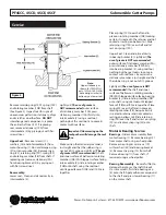
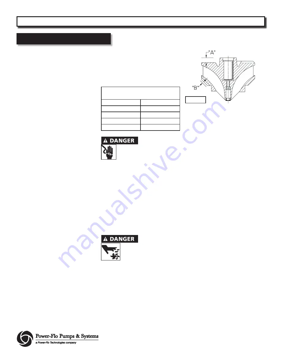
Check the gap (A) between the intermediate 

and upper portion of impeller with a feeler 

gauge which should be between .012” - 

.059”. Gap (B) between the lower portion 

of impeller and volute should be between 

.012” - .059”. See Figure 3. 

Cutter Height Adjustment -

 Loosen two 

screws (51) and bring the upper surface of 
the blade as close as possible to the lower 
heel of the impeller without touching and 
tighten firmly.

Cutter Angle Adjustment 

- Loosen two 

screws (45) and move the knife (42) across 
so as to bring blade flush up to the point 
of the impeller, permitted play between 
.002” - .005” and tighten firmly.

Cable Assembly -

 Loosen cable 

connectors (32) and (35), replace if 
required. Remove cap screws (19), 
washers (20) and cable box cover (5) from 
motor housing (1). Remove cable lead 
wires from motor lead wires and sensor 
wires from control cable by unscrewing 
connectors (31) and (32). Note wiring 
connections for reassembly. Remove 
screw (26), washer (27) and ground wire 
(30) from cover plate (5).

Service

PF4SCC, 4SCD, 4SCE, 4SCF    


 Submersible Cutter Pumps

Figure 3

Summary of Contents for PF4SCC Series

Page 1: ...SCF 4 2 8 9 17 7 29 9HP 3PH 230 460V 1150 1750 RPM 60 Hz Series PF4SCC 4 2 4 8HP 3PH 230 460V 1150 1750 RPM 60 Hz Series PF4SCD 4 2 4 8 7 1HP 3PH 230 460V 1150 1750 RPM 60 Hz Series PF4SCE 4 2 12 9 17...

Page 2: ...gers in pump with power connected The cuting mechanism is VERY SHARP Be extremely careful when servicing and or repairing the pump Always wear eye protection when working on pumps Do not wear loose cl...

Page 3: ...nless Steel SEAL Tandem Mechanical Oil Filled Reservoir Upper Carbon Stainless Buna N Lower Tungsten Carbide Tungsten Carbide Buna N SEAL PLATE Cast Iron POWER CORD 30 ft cord pressure grommet MOTOR N...

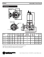
Page 4: ...0 457 0 57 PF4SCC4246 4 2 460 3 1150 100 6 4 31 5 2 45 G 4G1 5mm2 14 4 SO 0 457 0 57 PF4SCC4834 4 8 230 3 1750 100 14 4 80 1 21 H 4G1 5mm2 14 4 SO 0 457 0 57 PF4SCC4844 4 8 460 3 1750 100 7 2 40 1 21...

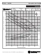
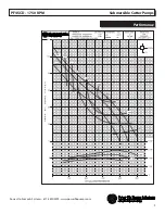
Page 5: ...5 Power Flo Pumps Systems 877 24PUMPS www powerflopumps com Performance PF4SCC 1150 RPM Submersible Cutter Pumps...

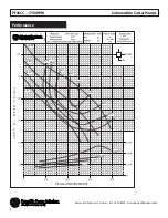
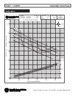
Page 6: ...6 Power Flo Pumps Systems 877 24PUMPS www powerflopumps com PF4SCC 1750 RPM Submersible Cutter Pumps Performance...

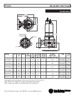
Page 7: ...SCD4834 4 8 230 3 1750 100 14 4 80 H 1 21 4G1 5mm2 14 4 SO 0 453 0 57 PF4SCD4844 4 8 460 3 1750 100 7 2 40 H 1 21 4G1 5mm2 14 4 SO 0 453 0 57 PF4SCD7134 7 1 230 3 1750 100 19 4 114 H 1 65 4G1 5mm2 14...

Page 8: ...8 Power Flo Pumps Systems 877 24PUMPS www powerflopumps com PF4SCD 1150 RPM Submersible Cutter Pumps Performance...

Page 9: ...9 Power Flo Pumps Systems 877 24PUMPS www powerflopumps com PF4SCD 1750 RPM Submersible Cutter Pumps Performance...

Page 10: ...SCE12934 12 9 230 3 1750 132 35 4 230 J 0 48 4G6mm2 10 4 SO 0 67 0 75 PF4SCE12944 12 9 460 3 1750 132 17 7 115 J 0 48 4G6mm2 10 4 SO 0 67 0 75 PF4SCE17734 17 7 230 3 1750 132 45 8 292 H 0 41 4G6mm2 10...

Page 11: ...11 Power Flo Pumps Systems 877 24PUMPS www powerflopumps com PF4SCE 1150 RPM Submersible Cutter Pumps Performance...

Page 12: ...12 Power Flo Pumps Systems 877 24PUMPS www powerflopumps com PF4SCE 1750 RPM Submersible Cutter Pumps Performance...

Page 13: ...CF8946 8 9 460 3 1150 132 12 8 75 H 0 64 4G6mm2 8 4 SO 0 67 0 78 PF4SCF17734 17 7 230 3 1750 132 45 8 292 H 0 41 4G6mm2 8 4 SO 0 67 0 78 PF4SCF17744 17 7 460 3 1750 132 22 9 146 H 0 41 4G6mm2 8 4 SO 0...

Page 14: ...14 Power Flo Pumps Systems 877 24PUMPS www powerflopumps com PF4SCF 1150 RPM Submersible Cutter Pumps Performance...

Page 15: ...15 Power Flo Pumps Systems 877 24PUMPS www powerflopumps com PF4SCF 1750 RPM Submersible Cutter Pumps Performance...

Page 16: ...id level should never be less than above the pump s volute See Figure 1 ThecutterpumpsareNOTdesignedtorun dry ThecasingMUSTbesubmerged Installation The cutter pumps can be installed in a wet well util...

Page 17: ...e Sensor To detec any moisture present a normally open N O probe is installed in the seal chamber The probe should be connected in series to an alarm device or motor starter coil to alert the operator...

Page 18: ...t electrical power to pump Disassembly Cutter Impeller Remove cap screws 45 and washer 47 from volute 40 Lift motor from volute 40 Clean out volute and check impeller for pitting or wear To replace im...

Page 19: ...USE IDENTIFICATION TAG ON EACH LEAD FIGURE 4 THREE PHASE 230 VOLT AC Power Cable Motor Lead Number G Ground G L1 or W1 1 7 L2 or W2 2 8 L3 or W3 3 9 T4 T5 T6 Together FIGURE 4 THREE PHASE 460 VOLT AC...

Page 20: ...ain it is seated in the retainer and not cocked or resting on bellows tail Slide retaining ring 10D over shaft and let rest on spring 10C Upper Seal Clean and oil seal cavity in bearing bracket 3 Ligh...

Page 21: ...Slide lower bearing and motor assembly into the bearing bracket 3 until bearing seats on the bottom Position bearing cap on some models on bearing bracket insert screws 19 with washers 20 and tighten...

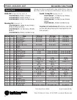
Page 22: ...flopumps com Figure 6 Repair Parts For Repair Part Please supply Model Number and MFG Date as shown on Name Plate and Part Description and Part Number as shown on Parts List PF4SCC 4SCD 4SCE 4SCF 100...

Page 23: ...UMPS www powerflopumps com Repair Parts For Repair Part Please supply Model Number and MFG Date as shown on Name Plate and Part Description and Part Number as shown on Parts List PF4SCF 180 Mtr Frame...

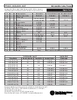
Page 24: ...dia 26 1 Screw H M4 x 6 H M4 x 6 H M4 x 6 27 1 Washer M 4 N M 4 N M 4 N 29 1 Power cable PF0 1852301 11X4G1 5 PF0 1852322 4G6 PF0 1852341 4G10 30 1 Ground 31 3 Wire connector 32 2 Cable connector PF0...

Page 25: ...rt Please supply Model Number and MFG Date as shown on Name Plate and Part Description and Part Number as shown on Parts List PF4SCC 4SCD 4SCE 4SCF Submersible Cutter Pumps Cutter Impeller item 41 Imp...

Page 26: ...26 Power Flo Pumps Systems 877 24PUMPS www powerflopumps com PF4SCC 4SCD 4SCE 4SCF Submersible Cutter Pumps Notes...

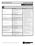
Page 27: ...hree phase reverse any two of three power supply leads to ensure proper impeller rotation 11 Repair fixtures as required to eliminate leakage 12 Check pump temperature limits and fluid temperature 13...

Page 28: ...od that has not been installed operated or maintained in accordance with Manufacturer s installation instructions that has been exposed to outside substances including but not limited to the following...

Reviews: