background image

5

Power-Flo Pumps & Systems • 877-24PUMPS • www.powerflopumps.com

PFEH  


     Submersible Effluent Pumps

Receiving Inspection

Upon receiving the pump, it should be 

inspected for damage or shortages.   

If damage has occurred, file a claim 

immediately with the company that 

delivered the pump. If the manual is 

removed from the packaging, do not 

lose or misplace.

Storage

Any product that is stored for a period 

longer than six (6) months from the 

date of purchase should be bench 

tested prior to installation.  A bench 

test consists of,  checking the impeller 

to assure it is free turning and a run 

test to assure the motor (and switch 

if provided) operate properly.  Do not 

pump out of liquid.

Controls

Manual models require a separate 

approved pump control device or panel 

for automatic operation.  Be sure the 

electrical specification of the control 

selected properly match the electrical 

specifications of the pump.

Submergence

The pump should always be operated in 

the submerged condition.  The minimum 

sump liquid level should never be less than 

above the pump’s volute (See Figure 1).

Installation

There are two methods of installing 
effluent pumps: 
1.) In a Flex-Hose system, most commonly 
used in interceptor tanks and.
2.) A slide rail in a package system or 
concrete wet well, which allows the 
pump(s) to be installed or removed 
without requiring personnel to enter 
the wet well.

The sump or  basin shall be sealed 

and vented in accordance with local 

plumbing codes. 

This pump is designed 

to pump effluent or wastewater, 

nonexplosive and noncorrosive liquids 

and shall NOT be installed in locations 

classified as hazardous in accordance 

with the National Electrical Code (NEC) 

ANSI/NFPA 70 or Canadian Electric 

Code (CEC).

 The pump should never be 

installed in a trench, ditch, or hole with 

a dirt bottom. The legs will sink into 

the dirt and the suction will become 

plugged.

The installation should be at a sufficient 
depth to ensure that all plumbing is 
below the frost line. If this is not feasible, 
remove the check valve and size the 
basin to accommodate the additional 
backflow volume.

Discharge Piping

Discharge piping should be as short 
as possible and sized no smaller than 
the pump discharge.  

Do not reduce 

the discharge pipe size below that 
which is provided on the pump.

  Both 

a check valve and a shut-off valve are 
recommended for each pump.  The 
check valve is used to prevent backflow 
into the sump.  The shut-off valve is 
used to manually stop system flow 
during pump servicing.

Liquid Level Controls

The level control(s) should be mounted 
on the discharge piping, a cable rack 
or float pole.  The level control should 
have adequate clearance so it cannot 
hang up in it’s swing and that the pump 
is completely submerged when the 
level control is in the “Off” mode.  By 
adjusting the cord tether the control 
level can be changed.  One cycle of 

operation should be observed, so that any 

potential problems can be corrected.

It is recommended that the level control 

float should be set to insure that the liquid 

in the sump never drops below the top of 

the motor housing or a minimum level of 
17 inches above the basin floor.

Electrical Connections

Power cable:

The power cable mounted to the pump 

must not be modified in any way except 

for shortening to a specific application.

Any splice between the pump and the

control panel must be made in 

accordance with the electric codes. It is

recommended that a junction box, if used, 

be mounted outside the sump or be of 

at a minimum Nema 4 construction if 

located within the wet well. 

DO NOT USE 

THE POWER CABLE TO LIFT PUMP. 

Always rely upon a Certified Electrician 

for installation.

Overload Protection:

Single Phase

 - The stator in-winding

overload protector used is referred to as 

an overheating protector and operates 

on the combined effect of temperature

and current. This means that the 

overload protector will trip out and shut 

the pump off if the windings become too 

hot, or the load current passing through 

them becomes too high. 

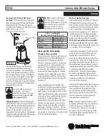
Receiving & Installation

Recommended

Submergence Level

Minimum

Submergence Level

Bottom of Feet

7”

Figure 1

Summary of Contents for PFEH Series

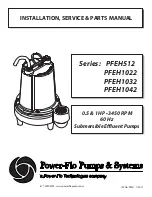
Page 1: ...877 24PUMPS www powerflopumps com 0 5 1HP 3450 RPM 60 Hz Submersible Effluent Pumps ISP No PFEH 1 2021 INSTALLATION SERVICE PARTS MANUAL Series PFEH512 PFEH1022 PFEH1032 PFEH1042 ...

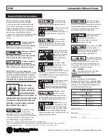
Page 2: ...th power connected Always wear eye protection when working on pumps Do not wear loose clothing that may become entangled in moving parts Pumps build up heat and pressure during operation Allow time for pumps to cool before handling or servicing This pump is not intended for use in swimming pools or water installations where human contact with pumped fluid Pumps when used as a decorative water foun...

Page 3: ...cal Oil Filled Silicon Carbide Silicon Carbide Buna N UPPER BEARING Single row ball oil lubricated LOWER BEARING Single row ball oil lubricated POWER CORD 15 Ft Cord Pressure Grommet for Sealing and Strain Relief MOTOR NEMA Design L Single Phase NEMA B Three Phase Class B Insulation SINGLE PHASE Permanant split capacitor Includes overload protection in motor THREE PHASE Requires overload protectio...

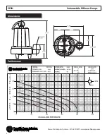
Page 4: ...4 Power Flo Pumps Systems 877 24PUMPS www powerflopumps com PFEH Submersible Effluent Pumps Dimensions Performance ...

Page 5: ...below the frost line If this is not feasible remove the check valve and size the basin to accommodate the additional backflow volume Discharge Piping Discharge piping should be as short as possible and sized no smaller than the pump discharge Do not reduce the discharge pipe size below that which is provided on the pump Both a check valve and a shut off valve are recommended for each pump The chec...

Page 6: ...d Perform the following checks when pump is removed from operation or when pump performance deteriorates a Inspect motor chamber for oil level and contamination b Inspect impeller and body for excessive build up or clogging c Inspect motor and bearings d Inspect seal for wear or leakage Servicing NOTE Item numbers in refer to Figure 6 Cooling Oil Anytime the pump is removed from operation the cool...

Page 7: ... 2 To reassemble clean the threads with thread locking compound cleaner Apply removable Loctite 242 or equivalent to shaft threads Screw impeller 2 onto the shaft hand tight while using a screwdriver in the slot at the end of the shaft to hold it stationary Install impeller nut 10 and tighten Rotate impeller to check for binding Position gasket 12 on volute flange and position impeller and motor ho...

Page 8: ...is lined up on rotating member 5b and not cocked or resting on bellows tail Place conduit bushing 25 and washer 26 onto shaft Slide rotor shaft 6 with bearing 7 and seal 5 into seal plate 3 until bearing 7 seats into seal plate Locate washer 26 into place on bearing and tighten conduit bushing 25 onto seal plate 3 Place stator 6 over rotor 6 lining up motor bolts with holes in seal plate 3 Positio...

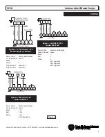
Page 9: ... Cable Motor Lead Number Green Ground Green Black 1 7 Red 2 8 White 3 9 4 5 6 Together Power Cable Motor Lead Number Green Ground Green Black 1 Red 2 White 3 4 7 Together 5 8 Together 6 9 Together Figure 5 Service PFEH Submersible Effluent Pumps Figure 5 115 230 Volt AC 1Ph Models PFEH512 PFEH1022 Figure 5 230 Volt AC 3Ph Models PFEH1032 Figure 5 460 Volt AC 3Ph Models PFEH1042 ...

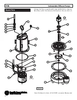
Page 10: ... 877 24PUMPS www powerflopumps com Repair Parts For Repair Part Please supply Model Number and MFG Date as shown on Name Plate and Part Description and Part Number as shown on Parts List Figure 6 PFEH Submersible Effluent Pumps ...

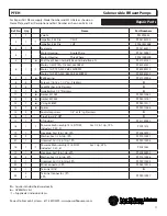
Page 11: ...g PF31020008 8 4 Screw 5 16 18 x 1 1 2 Lg Stainless 9 4 Lock Washer 5 16 Stainless 10 1 Impeller Nut 1 2 Stainless 11 1 Gasket 27269 PF92010082 12 1 Gasket 27344 PF92010147 13 1 V ring 56789 PF92010111 14 1 Spacer PF92010086 15 2 Soc Hd cap screw 1 4 x 3 4 Lg Stainless 16 1 Pipe Plug 3 4 NPT 17 1 Lifting bail PF31120002 18 1 Power cable Assembly 14 3 SJTOW For 1 2 1 Hp 1 Ph Includes 19 20 21 PF091...

Page 12: ...Effluent Pumps 25 1 Conduit Bushing PF31190022 26 1 Washer Bushing PF91010053 27 2 6 Female Connector 1Ph 3Ph PF94010041 28 8 Gal Cooling Oil See Chart on Page 7 Aquire Locally 29 1 Capacitor PF31030031 30 1 Clamp PF93010001 31 1 Wire Connector PF94010011 OVERHAUL KIT Kit to include shaft seal 5 bearing 7 impeller nut 10 gasket 11 gasket 12 v ring 13 spacer 14 conduit bushing 25 washer 26 PFEH OHK...

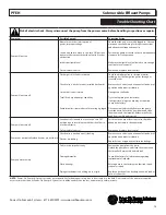
Page 13: ...p may be required Consult the factory Disconnect unit electrically Remove the pump from the basin Detach the pump base and clean the area around the impeller Rotate impeller by hand Reassemble and reinstall Pump will not turn off Level control s unable to move to the turn OFF position due to interference with the side of basin or other obstacle Defective level control Posistion the pump or level c...

Page 14: ...14 Power Flo Pumps Systems 877 24PUMPS www powerflopumps com Notes PFEH Submersible Effluent Pumps ...

Page 15: ...15 Power Flo Pumps Systems 877 24PUMPS www powerflopumps com Notes PFEH Submersible Effluent Pumps ...

Page 16: ...t has not been installed operated or maintained in accordance with Manufacturer s installation instructions that has been exposed to outside substances including but not limited to the following sand gravel cement mud tar hydrocarbons hydrocarbonderivatives oil gasoline solvents etc orotherabrasiveorcorrosivesubstances wash towels or feminine sanitary products etc in all pumping applications The w...

Reviews: