7
Power-Flo Pumps & Systems • 877-24PUMPS • www.powerflopumps.com
Pressure Test (If oil has NOT been
drained) -
Oil should be at normal level.
Remove pipe plug (16) from housing (4).
Apply pipe sealant to pressure gauge
assembly and tighten into hole. Pressurize
motor housing to 10 P.S.I.
Use soap solution around the sealed
areas above the oil level and inspect
joints for “air bubbles”. For sealed areas
below oil level, leeks will seep oil. If, after
five minutes, the pressure is still holding
constant, and no “bubbles” /oil seepage
is observed, slowly bleed the pressure
and remove the gauge assembly. Replace
oil. Leek must be located and repaired if
pressure does not hold.
Pressure builds up extremely
fast, increase pressure by
“TAPPING” air nozzle. Too much
pressure will damage seal.
DO
NOT exceed 10 P.S.I.
Oil Replacement
- Set unit upright and
refill with new cooling oil as per table. Fill
to just above motor, (but below capacitor,
on 1 phase units) as an air space must
remain in the top of the housing to
compensate for oil expansion. Apply pipe
thread compound to threads of pipe plug
(16) then assemble to housing (4).
DO NOT
overfill oil. Overfilling
of housing with oil can create
excessive and dangerous hydraulic
pressure which can destroy the
pump and create a hazard.
Overfilling oil voids warranty.
102 oz - Cooling Oil
Recommended Supplier/Grade
BP
Enerpar SE100
Conoco
Pale Paraffin 22
Mobile
D.T.E. Oil Light
Shell Canada
Transformer-10
Texaco
Diala-Oil-AX
Disassembly & Assembly
Impeller, V-ring and Volute:
Disconnect power. Remove cap screws (8)
and lock washers (9) vertically lift motor,
housing and seal plate assembly from
volute (1). Clean out volute (1) if necessary.
Inspect gasket (12) and replace if cut or
damaged. Clean and examine impeller
(2), for cracks or breakage and replace if
required. To remove impeller (2), remove
impeller nut (10), place a flat screwdriver
in the slot of the end of the shaft to hold
the shaft stationary while unscrewing the
impeller (2).
To reassemble, clean the threads with
thread locking compound cleaner. Apply
removable Loctite® 242 or equivalent to
shaft threads. Screw impeller (2) onto the
shaft hand tight while using a screwdriver
in the slot at the end of the shaft to hold
it stationary. Install impeller nut (10)
and tighten. Rotate impeller to check for
binding. Position gasket (12) on volute
flange and position impeller and motor
housing assembly on volute (1). Position
lock washer (9) on cap screw (8) and screw
into volute (1). Torque to 100 in-lbs. Check
for free rotation of impeller.
Motor, Capacitor, Bearings:
Place pump upright on blocks or piece of
PVC pipe, to avoid resting unit on shaft.
Disassemble volute and impeller as stated
and drain oil from housing. Loosen gland
nut (19) and slide up cord along with
washers (20) and grommet (21). Remove
socket head screws (15) from seal plate
(3). Slide motor housing (4) up cable (18)
until wire connectors (24) are exposed.
NOTE wire connections for reassembly.
Disconnect cable leads from motor leads
and remove motor housing (4) and o-ring
(11), replace if cut or damaged.
Check motor capacitor (29) with an Ohm
meter by first grounding the capacitor
by placing a screwdriver across both
terminals and then removing screwdriver.
Connect Ohm meter (set on high scale) to
terminals. If needle moves to infinity (
∞
)
then drifts back, the capacitor is good. If
needle does not move or moves to infinity
(
∞
) and does not drift back, replace
capacitor (29). Inspect motor winding
for shorts and check resistance values.
Check rotor for wear. If rotor or the stator
windings are defective, the complete
motor must be replaced.
Disconnect capacitor leads from capacitor
(29). Remove v-ring (13) and spacer (14)
from seal plate (3). Remove bolts from
motor stator (6) and lift stator up from
rotor. Loosen conduit bushing (25) and
remove motor rotor, bearing and seal
assembly from seal plate (3).
SEAL -
Remove rotating member (5b),
spring (5c) and retaining ring (5d), from
shaft (see Figure 3). Inspect for signs
of uneven wear pattern on stationary
member, chips and scratches on either
seal face. Replace the complete seal if
any part is damaged.
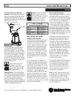
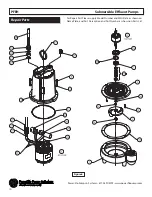
Figure 2
Service
PFEH
Submersible Effluent Pumps

