background image

8

Power-Flo Pumps & Systems • 877-24PUMPS • www.powerflopumps.com

Pre-Operation

1.   Check Voltage and Phase


Compare the voltage and phase


information stamped on the pump 


name plate.

2.   

Check Pump Rotation

 - Improper 


motor rotation can result in poor 


pump performance and can damage


the motor and/or pump. Check 


rotation on three phase units by 


momentarily applying power and 


observe the “kickback”.  Kickback 


should always be in a counter-


clockwise direction as viewed 


from motor end or opposite to 


impeller rotation. Incorrect rotation 


for Single-Phase pumps is unlikely. 


If the rotation is incorrect contact 


factory.

3.   

Name Plate

 - Record the information


from the pump name plate to 


drawing in front of manual for future 


reference.

4.  

Insulation Test

 - An insulation 


(megger) test should be performed 


on the motor.  Before the pump is put 


into service. The resistance values 


(ohms) as well as the voltage (volts) 


and current (amps) should be 


recorded.

Maintenance

No lubrication or maintenance is required. 

Perform the following checks when  pump 

is removed from operation or when pump 

performance deteriorates:

a).   Inspect motor chamber for oil level 


and contamination.

b).  Inspect impeller and body for 


excessive build-up or clogging.

c).  Inspect and clean screen if required.

d).  Inspect seal for wear or leakage.

Servicing

NOTE: Item numbers in ( ) refer to Figures 

3 & 4.

 WARNING ! - Before any service 

 work is done, disconnect and  

 lock out electrical power to 

 pump.

Cooling Oil - 

Anytime the pump is 

removed from operation, the cooling oil 

in the motor housing should be checked 

visually for oil level and contamination.

To check oil, set unit upright. Remove 

pipe plug (32).   With a flashlight, visually 

inspect the oil in the housing tube (27) 

to make sure it is clean and clear, light 

amber in color and free from suspended 

particles. Milky white oil indicates the 

presence of water. Oil level should be 

above all internal componentry.

Oil Testing

•  Drain oil into a clean, dry container by

  placing pump on it’s end, remove pipe 

  plug (32), from housing tube (27). 

•  Check oil for contamination using an 

  oil tester with a range to 30 Kilovolts 

  breakdown.

•  If oil is found to be clean and 

  uncontaminated (measuring above 

  15 KV. breakdown), refill the housing.

•  If oil is found to be dirty or contaminated 

  (or measures below 15 KV. breakdown), 

  the pump must  be carefully inspected for

  leaks at the shaft seal (8), gland nut (17), 

  o-rings (23), and pipe plug (32), before 

  refilling with oil. To locate the leak, 

  perform a pressure test.

After leak is repaired, dispose of old oil 

properly, and refill with new oil.

Oil Replacement 

- Set unit upright and 

(drain oil, if not already done), refill with 

new cooling oil as per table below. 

An air space must remain in the top of 

the housing tube when pump is placed 

with volute end on bench, to compensate 

for oil expansion. Fill until capacitor is 

covered when viewing through fill plug 

hole. When refilling with oil after servicing 

the shaft seal (8), a pressure test should 

be preformed. If shaft seal (8) was not 

serviced, then apply pipe sealant and 

replace the pipe plug (32).


DO NOT

 overfill oil. Overfilling 

 of housing with oil can create 

 excessive and dangerous hydraulic

pressure which can destroy the

pump and create a hazard. 

Overfilling oil voids warranty.

Cooling Oil

Recommended Supplier/Grade

BP

Enerpar SE100

Conoco

Pale Paraffin 22

Mobile

D.T.E. Oil Light

Shell Canada

Transformer-10

Texaco

Diala-Oil-AX

Pressure Test -

 Oil should be at normal 

level. Remove pipe plug (32) from housing 

end (19).  Apply pipe sealant to pressure 

gauge assembly and tighten into hole. 

Pressurize housing to 6 P.S.I.  Use soap 

solution around the sealed areas and 

inspect joints for “air bubbles”.  If, after 

five minutes, the pressure is still holding 

constant, and no “bubbles” /oil seepage 

is observed, slowly bleed the pressure 

and remove the gauge assembly. Replace 

pipe plug using sealant. The leek must be 

located and repaired if pressure does not 

hold.

 Pressure builds up  extremely
 fast, increase   pressure by 

“TAPPING” air nozzle. Too much  
 pressure will damage seal. 
 

DO NOT  exceed 6 P.S.I.

Pre-Operation & Service

PFU31, PFU51, PFU71, PFU102, PFU152, PFU202 

     Submersible Fountain Pumps

Summary of Contents for PFU102 Series

Page 1: ...877 24PUMPS www powerflopumps com ISP No PFU_b 1 2021 INSTALLATION SERVICE PARTS MANUAL Series PFU31 PFU51 PFU71 PFU102 PFU152 PFU202 1 3 1 2 3 4 1 1 1 2 2HP 3450 RPM 60 Hz Submersible Fountain Pumps...

Page 2: ...ye protection when working on pumps Do not wear loose clothing that may become entangled in moving parts Pumps build up heat and pressure during operation Allow time for pumps to cool before handling...

Page 3: ...ical Carbon Ceramic Buna N POWER CORD 12 Ft MOTOR END BEARING Single Row Ball Oil Lubricated PUMP END BEARING Single Row Ball Oil Lubricated MOTOR Oil Filled Squirrel Cage Induction NEMA B Design Clas...

Page 4: ...4 Power Flo Pumps Systems 877 24PUMPS www powerflopumps com Dimensions Performance PFU31 PFU51 PFU71 PFU102 Submersible Fountain Pumps...

Page 5: ...ricated PUMP END BEARING Single Row Ball Oil Lubricated MOTOR Oil Filled Squirrel Cage Induction NEMA B Design Class H Insulation SINGLE PHASE Permanent Split Capacitor PSC Includes Overload Protectio...

Page 6: ...6 Power Flo Pumps Systems 877 24PUMPS www powerflopumps com Dimensions Performance PFU152 PFU202 Submersible Fountain Pumps...

Page 7: ...tomatic overload protector and does not require a control box Connect the white and black wires of the motor lead to the two line leads from the power source fused disconnect switch or breaker box Con...

Page 8: ...ump on it s end remove pipe plug 32 from housing tube 27 Check oil for contamination using an oil tester with a range to 30 Kilovolts breakdown If oil is found to be clean and uncontaminated measuring...

Page 9: ...nding the capacitor by placing a screwdriver across both terminals and then removing screwdriver Connect Ohm meter set on high scale to terminals If needle moves to in nity then drifts back the capaci...

Page 10: ...riction ring into housing end piece 19 Apply pipe sealant to gland nut 17 screw into end piece and torque gland nut to 17 5 ft lbs to prevent water leakage Service For Repair Part Please supply Model...

Page 11: ...pair Parts Bearing Design For Repair Part Please supply Model Number and MFG Date as shown on Name Plate and Part Description and Part Number as shown on Parts List Figure 4 PFU31 PFU51 PFU71 PFU102 P...

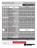
Page 12: ...0 Stainless 21 10 Lockwasher 1 4 22 2 Pump support PF023316 PF023316 PF023316 PF023316 23 2 O ring Buna N PF016068 PF016068 PF016068 PF016068 24 2 Terminal Connector Plastic PF079318 PF079318 PF079318...

Page 13: ...ockwasher 1 4 22 2 Pump support PF61PFU1503 PF61PFU1503 23 2 O ring Buna N 156 ID x 3 5mm PF63PFU1501 PF63PFU1501 24 2 Terminal Connector Plastic PF079318 PF079318 25 1 Capacitor bracket Steel PF03985...

Page 14: ...ply Model Number and MFG Date as shown on Name Plate and Part Description and Part Number as shown on Parts List Repair Parts Sleeve Design For Repair Part Please supply Model Number and MFG Date as s...

Page 15: ...dings are defective the complete motor must be replaced To test the overload check the continuity between the black and white wires Assemble bearing sleeve 9 onto motor 10 locating overload as noted o...

Page 16: ...m Repair Parts Sleeve Design For Repair Part Please supply Model Number and MFG Date as shown on Name Plate and Part Description and Part Number as shown on Parts List Figure 4 For Units previous to J...

Page 17: ...F086039 19 1 Housing end Brass PF026850 PF026850 PF026850 PF026850 20 10 Hex nut 1 4 20 Stainless 21 10 Lockwasher 1 4 22 2 Pump support PF023316 PF023316 PF023316 PF023316 23 2 O ring Buna N PF016068...

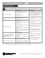
Page 18: ...quired to eliminate leakage 11 Check pump temperature limits and fluid temperature 12 Replace portion of discharge pipe with flexible connector or tighten existing piping 13 Check screen and or suctio...

Page 19: ...19 Power Flo Pumps Systems 877 24PUMPS www powerflopumps com PFU31 PFU51 PFU71 PFU102 PFU152 PFU202 Submersible Fountain Pumps Notes...

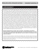
Page 20: ...accordance with Manufacturer s installation instructions that has been exposed to outside substances including but not limited to the following sand gravel cement mud tar hydrocarbons hydrocarbonderi...

Reviews: