Power-Flo Pumps & Systems • 877-24PUMPS • www.powerfl opumps.com
2
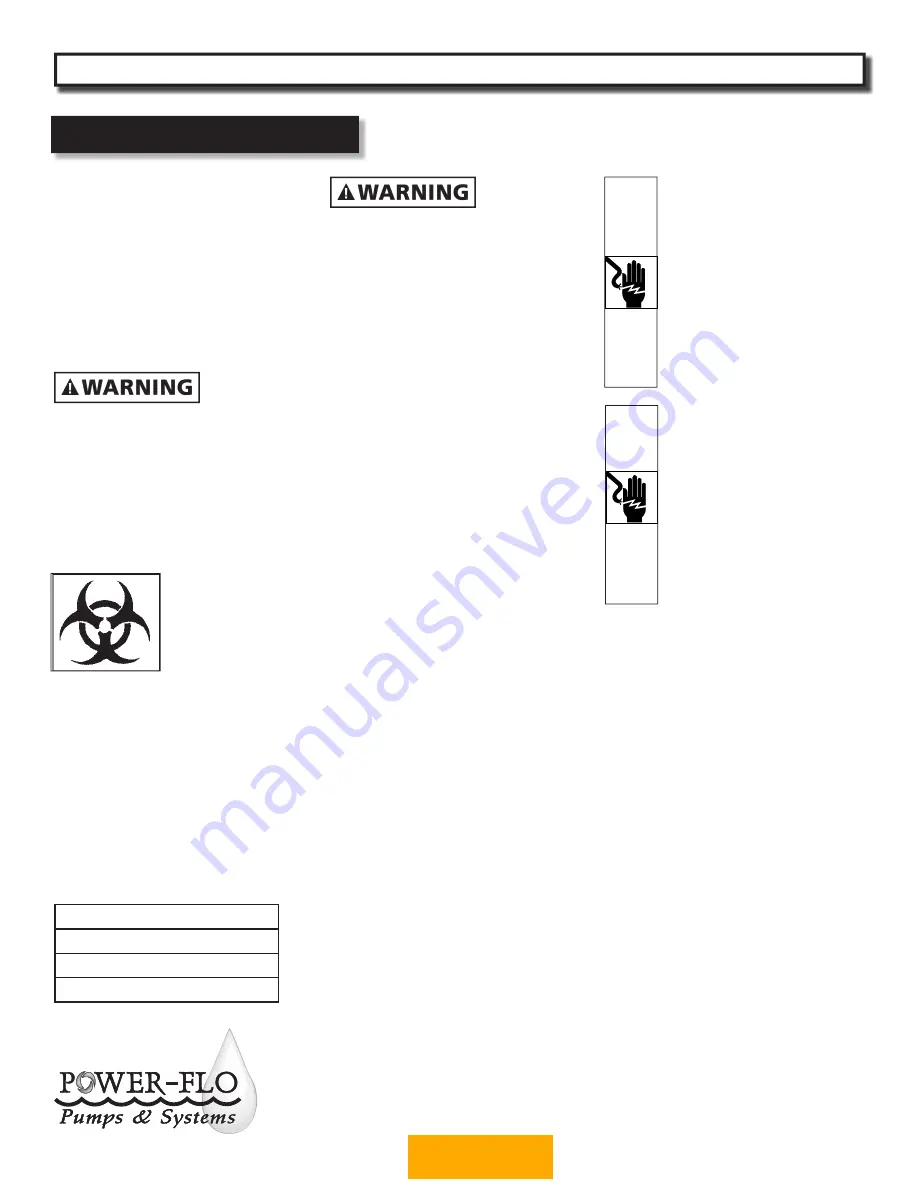
Before installation, read the following
instructions carefully. Failure to follow
instruction and Safety information
could cause serious bodily injury,
death and/or property damage. Each
Power-Flo pump is individually factory
tested to insure proper performance.
Closely following these instructions will
eliminate potential operating problems,
assuring years of trouble-free service.
• Risk of electric shock. To reduce risk of
electric shock, always disconnect pump
from power source before handling.
Lock out power & tag.
• Installation must be in accordance
with the National Electric Code and all
applicable state and local codes.
ALL RETURNED
PRODUCTS MUST BE
CLEANED,
SANITIZED, OR
RECONTAMINATED
PRIOR TO SHIPMENT,
TO INSURE EMPLOYEES WILL NOT
BE EXPOSED TO HEALTH HAZARDS
IN HANDLING SAID MATERIAL.
ALL APPLICABLE LAWS AND
REGULATIONS SHALL APPLY.
• Installation and servicing is to be
conducted by qualifi ed personnel.
• These pumps are NOT to be installed
in locations classifi ed as hazardous in
accordance with the National Electric
Code, ANSI/NFPA 70.
• Keep clear of suction and discharge
openings. Do not insert fi ngers in
pump with power connected.
• Always wear eye protection when
working on pumps.
•
DO NOT
use power cord to lift pump.
Protect cable from cuts and punctures.
Do not handle power cable with wet
hands.
•
DO NOT
us these pumps in water over
77˚F.
• Pumps build up heat and pressure
during operation-allow time for pumps
to cool before handling or servicing.
This pump is
NOT
intended for
use in swimming pools or any
body of water with human
contact. Pumps when used as a
decorative water fountain
pump
MUST
be used in circuit
protected by a Ground Fault
Interrupter. Installations in
Decoritive Fountains or Water
Features provided for visual
enjoyment MUST be installed
per ALL State and Local codes.
RISK OF ELECTRIC SHOCK,
DEATH OR PERSONAL INJURY.
If basement fl oor has water
or moisture on it, do not
walk on this area until ALL
power has been turned OFF.
If main breaker is in this area,
call electric authority to shut-
off service, or call local fi re
department for assistance or
instructions before attempting
to service pump.
PFUT06, PF30A
Portable Utility Pumps
General Safety Information
® Power-Flo is a registered trademark of Power-Flo Technologies Inc.
Other brand and product names are trademarks or registered trademarks of their respective holders.
Alteration Rights Reserved. 4/08, 1/09, 2/09, 6/09, 4/10
IMPORTANT!
Prior to installation, record Model
Number, MFG Date,
and/or serial number, from pump
name plate for future reference.
Model:
Serial:
MFG Date:
BACK TO INDEX


