background image

Page 7

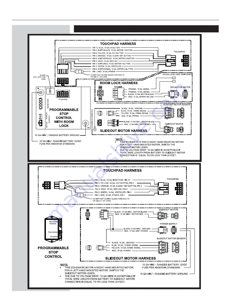
Wiring Diagram

Programmable Stop Control Wtih Room Locks

Programmable Stop Control

Summary of Contents for 1510000120

Page 1: ...stallation Installation Problems Program Mode Operation Mode Preventative Maintenance Fault Diagnostics Troubleshooting Override Modes Wiring Diagram 6 7 7 P N 81 1291 for proper installation of rail assemblies installation of room locks Control and touchpad Installation Refer to proper wiring diagram in back of manual B B nents from the elements and being hit but is easily accessible for service ...

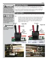
Page 2: ...he control is also equipped to help troubleshoot the system during installation Count the number of LED flashes and refer to Fault Diagnostics section previous If you are still having difficulties programming the system and prior to replacing the control verify the system has been wired correctly and the in stop location was programmed before the out stop location was programmed CAUTION S WARNING ...

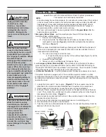
Page 3: ... motor rotation must be determined and programmed with the control Ref Step 2 Damage to the room or system may result Once control has been programmed correctly this step will not need to be repeated CAUTION S WARNING S Prior to extending or retracting the room take a moment to insure the following 1 Follow the coach manufacturer instructions regarding the leveling of the coach and room slide out ...

Page 4: ...cting the room take a moment to insure the following 1 Follow the coach manufacturer instructions regarding the leveling of the coach and room slide out operation 2 Verify the battery is fully charged Keeping the coach running will ensure proper voltage for room extension retraction 3 Park brake must be set 4 Check both inside and outside of the vehicle to make sure there are no people who could b...

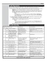
Page 5: ...or Excessive Battery Voltage Bad battery Replace battery Battery Voltage is above 18 0V when room movement was initiated 5 Minor Slideout motor drawing Excessive system room drag Remove obstruction re adjust room reset excessive current obstruction improper stop stops or replace damaged locations or damaged component component 6 Major Slideout Motor Short Shorted wiring or motor Inspect motor harn...

Page 6: ...tor sensing control harness has been unplugged do not attempt to use the room again until a service center has reprogrammed the computerized controller according to the service manuals instructions Failure to reset the controller may cause damage to the system or coach Page 6 Override Modes WARNING S WARNING S CAUTION S B H Your system can be manually overridden During override mode the control ha...

Page 7: ...Page 7 Wiring Diagram Programmable Stop Control Wtih Room Locks Programmable Stop Control ...

Page 8: ...Page 8 Additional References located at www lci1 com 3010001346 Owners Manual Room Slideout System with Control Box 1510000120 and 1510000121 82 SO539 Encoder Test 1 82 SO540 Encoder Test 2 ...

Reviews: