SS3L / SS3R Series
www.powergenex.com
51
12.
Maintenance / Service
12.1.
Preliminary Check Points
12.1.1.
Voltage
- The positioner commonly requires 4-20mA @ 24VDC for operation.
- Voltage drop (impedance): Without HART – 8.7VDC (435Ω @ 20mA)
With HART – 9.4VDC (470Ω @ 20mA)
12.1.2.
Electrical Connections
Check polarities (+, -) of 4-20mA input signal definitely and make the electrical connections.
12.1.3.
Pneumatic Connections (see 8.1, 8.2)
12.1.4.
Supply Air Quality
A supply air should be definitely clean and compressed free of water, moisture or oil in
conformance with IEC 770 and ISA-7.0.01.
12.2.
Module Parts
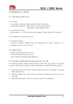
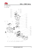
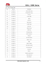
① RTQ Coil Assembly (spare part No. 12)
② Pilot Valve Assembly (spare part No. 5)
③ PCB Control Board Assembly (spare part No. 3)
12.3.
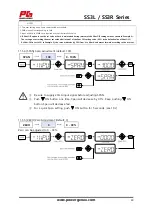
Re-setting of Potentiometer (spare part No. 14a, 14b)
It is necessary to adjust a setting of potentiometer as below when a gear position is moved due
to user’s carelessness. For reference, 0~10kΩ potentiometer is installed into the SS2 positioner.
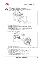
① Dis-install the electronic card from the SS3 positioner and make the markings on two gears
match with each other.
② Move the feedback lever to 50% position and adjust a potentiometer so that it can reach
nearly 5kΩ.
③ Re-install the SS3 positioner onto the valve and re-perform auto-calibration.

