Get the most out of your Power Plus Supertilt Plus with the comprehensive Owner's Manual. Easily download this essential manual from our website for free, ensuring that you have all the necessary information to optimize your product's performance.
POWER PLUS MOBILITY
1214 Kamato Road, Mississauga, Ontario, L4W 1Y1 Tel: (905) 614 0333 Toll Free (855) 614 0333 Fax: (905) 614 0435
WWW.POWERPLUSMOBILITY.COM
Page 1: ...POWER PLUS MOBILITY 1214 Kamato Road Mississauga Ontario L4W 1Y1 Tel 905 614 0333 Toll Free 855 614 0333 Fax 905 614 0435 WWW POWERPLUSMOBILITY COM ...
Page 2: ...nd we want to guarantee it However we suggest you regularly inspect your chair checking for loose fasteners excess play and damage We also strongly recommend that regular maintenance be done by your servicing dealer Please complete your Warranty registration card and return it to us at Power Plus Mobility Also please read this manual to help you understand the proper operation safety and maintenan...
Page 3: ...ts in workmanship and material to the original owner for a period of 5 years This warranty is invalid if the chair has been damaged by accident misuse neglect improper application unauthorized service repair or the addition of non factory approved accessories Power Plus Mobility will repair or replace defective parts as required A return authorization must be obtained and the parts returned to us ...
Page 4: ...d casters should also be cleaned with a mild soap and water solution LUBRICATION Your wheelchair has been made with low friction plastic chromoly aluminum and polished chrome to reduce friction and wear However a light use of thin lubricant such as WD40 or silicone spray will reduce friction and wear making your chair easier to use SAFETY AND HANDLING The safe handling of your chair depends on und...
Page 5: ...ard and down very slowly It is a definite no no to use your chair on an escalator find the nearest elevator instead Going up or down stairs should be done with at least two attendants at all times TRANSFERRING IN A WHEELCHAIR Attendant assistance is recommended to stabilize the chair and help in lifting you if necessary Transfers are best accomplished by following these guidelines Use a chair with...
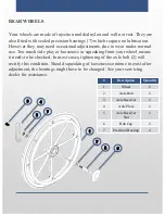
Page 6: ...ide play or looseness or squeaking from your wheel means it needs to be checked In most cases tightening of the axle bolt 2 will rectify this condition Should squeaking of looseness continue to exist after adjustment the bearings might have to be changed See your servicing dealer for assistance Description Quantity 1 Wheel 2 2 Axle Bolt 2 3 Axle Receiver 2 4 Axle Plate 2 5 Axle Receiver Nut 2 6 Hu...
Page 7: ... position of the wheel lock is pre set at the factory to provide you with the safest performance However with tire and brake shoe 3 wear they may have to be occasionally adjusted to ensure safety To adjust loosen the bracket bolts 5 and slide brake assembly 2 towards wheel Ensure that the brake holds securely but does not require too much effort to be applied Then tighten the bracket bolt securing...
Page 8: ...ttering or pulling is experienced your stem bearings 9 may need adjustment or replacements To adjust flip chair back onto its push handle and remove the dust caps 1 on the caster sockets Tighten the fork stem nut 2 clockwise while holding the caster assembly Check for smooth easy turning without side or end plays while adjusting do not over tighten as this may damage the bearings Number Descriptio...
Page 9: ...ve it from the frame To adjust the Anti Tipper height Pull on 4 while moving 2 to your desired position release 4 to lock into place Please adjust your Anti Tippers to a safe height maximum 2 from the ground Whenever the seat height is adjusted by wheels the Anti Tipper height must be adjusted as well Description Quantity 1 Bolt 1 2 Height Extension Tube 1 3 Housing 1 4 Locking Pin 1 5 Anti Tipper...
Page 10: ... mechanism It will swing to the side of your chair and could then be removed by lifting it straight up and off the locating pins 3 To replace hold footrest at the side of your chair locate onto mounting pins allowing it to drop all the way in and then push forward until it locks into place Number Description Quantity 1 Foot Plate 2 2 Release Handle 2 3 Mounting Pins 4 4 Footrest Extension Tube 2 1...
Page 11: ...t while the footrest is in a down position Lifting on the footplate raises the legrest and it will automatically lock at the raised position 1 2 Number Description Quantity 1 Legrest Release Assembly 2 2 Legrest Hanger 2 Pulling back on the black coated tab 1 on the elevating locking device lowers the legrest Pull up on 2 to raise the legrest ...
Page 12: ...hen lift arm top 1 straight up evenly near the back of the arm When the arm is returned to the closed position and pushed down the locking pin will relock Number Description Quantity 1 Arm Top 2 2 Arm Base 2 3 Arm Removal Latch 4 1 2 3 Adjustable height arms provide 5 adjustment positions To adjust pull out and hold the height adjustment release knob Then lift up or push down the arm top to achiev...
Page 13: ... frame This cylinder is activated by a cable mounted on the right push handle of your chair To tilt your chair squeeze the release handle and push downward on the push handle When the required degree of tilt is achieved release the handle and the chair will lock at this angle Tilting could be done as many times as required To bring back your chair to an upright position squeeze the handle push upw...
Page 14: ...ne capability To recline your chair squeeze the release handle and push downward on the push handle until the required degree of recline is achieved Then release the handle and the chair will lock at this angle Reclining could be done as often as necessary To bring your chair back up to an upright position squeeze the handle push upwards until back is upright then release the handle Your cylinder ...
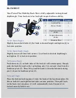
Page 15: ... both sides of the back it will remain open Simply push the back forward so the top locking pin 1 is out and clear from the hardware plate 5 Then lift up and forward to clear the bottom locking pin 1 from the hardware plate 5 To Install Back Place the bottom locking pins 1 into the hook of the hardware plate Do this so both left and right bottom sides are into position Then pull back on the back r...
Page 16: ...n 3 to lock the headrest into position To set Vertical Adjustments Simply loosen 5 and set 4 to your desired height Then tighten 5 to lock the height of your headrest Please set your headrest to accommodate your comfort level Number Description Quantity 1 Headrest Pad 1 2 Horizontal Extension Tube 1 3 Horizontal Adjustment Knob 1 4 Vertical Extension Tube 1 5 Vertical Adjustment Knob 1 5 4 2 3 1 ...
Page 17: ...nt Bracket Front 2 5 Lower Frame Cylinder Mount Bracket Front 2 4 5 2 1 3 Seat Height Adjustments By Frame Standard Frame Frame Bracket 1 Cylinder Mount 1A 5A 3A Right Cylinder 500N 4B 2A Left Cylinder 400N Low Frame Frame Bracket 1 Cylinder Mount 1B 5A 3B Right Cylinder 500N 4A 2A Left Cylinder 400N A B A A B A B REAR FRONT A Weight Setup 0 165 lbs 400 N left x 500 N right 165 225 lbs 200 N left ...