background image

CF(M)-3K-12 SUPERCOMBI USER’S GUIDE

14

3. Installation Instruction

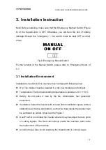
Note: Before installing, make sure that the Emergency Manual Switch (Figure

6) of the SuperCombi is OFF. Otherwise, you will face the risk of battery

damage! Except the "emergency ", this switch must be kept OFF at other

times.

Fig 6. Emergency Manual Switch

For the function of the Manual Switch, please refer to ‘Emergency Mode’ of

5.7.

3.1 Installation Environment

Installation site of All-in-One machine must comply with following roles:

Dry: The inverter must be installed in a dry, low moisture environment.

Temperature: The full-load working temperature is between -20

~+50

.

Safety: Do not place it near by the fire, inflammable, fuel, generator

equipment.

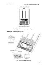
Ventilation: Install the inverter with at least 30mm ventilation space without

obstruction at the top and bottom, so that the heat inside the product can

be ventilated by airflow. Shown as the Figure 7.

Dust Proof: Do not install the inverter where it may be subject to dust, grind,

or cutting ingress. The dust can build-up inside the machine, and cause

the malfunction of the machine.

AvoidCorrosive Gas: Avoid exposing the SuperCombi to corrosive gas.

Summary of Contents for CF-3K-12 Series

Page 1: ...1 Series CF M 3K 12 Inverter Charger MPPT SuperCombi User Manual PowerPlus Australia Group Pty Ltd ...

Page 2: ...ve these instructions properly may result in personal damage or personal injury which depending on the circumstances may be serious and cause loss of life DISCLAIMER PowerPlus Australia Group Pty Ltd accepts no liability for any loss or damage which may occur from the improper or unsafe use of its products Warranty is only valid if the unit has not been modified or misused by the customer ...

Page 3: ...generated by the short circuit of the battery is very large and it is possible to weld and burn the metal which can cause severe burns 9 This product is not intended for use by persons including children with reduced physical sensory or mental capabilities or lack of experience and knowledge unless they have been given supervision or instructions concerning the use of the appliance by a person res...

Page 4: ...1 2 3 Wiring Cabin 11 2 4 Display Settings Panel 12 3 Installation Instruction 14 3 1 Installation Environment 14 3 2 System Wiring Diagram 15 3 3 Cabling 16 3 4 Match the Battery and Current 17 4 Basic Settings 17 4 1 Battery Type 17 4 2 Charge Current 18 4 3 Grid Limit 19 4 4 Auto Invert 20 4 5 Float Charge 21 5 Operation Guide 21 5 1 Invert 21 5 2 Energy Save Mode 21 5 3 AC Charge 22 5 4 PV Cha...

Page 5: ...ority 26 6 4 On Grid Supply 26 6 5 Separate Supply 27 6 6 Wire Compensation 27 6 7 Battery Capacity Testing 28 6 8 Start Battery Charging 28 7 Extended Functions 29 7 1 Charger Inverter Parameter Customization 29 7 2 Temperature Compensation 29 7 3 Dead Battery Charging 29 8 Specifications 31 9 Troubleshooting 33 10 Appendices 36 11 Warranty 37 ...

Page 6: ...module is so compact that it can be installed inside the machine All the resources including the cable the screen the cooling system can be shared Loads Priority and On Grid Compensation function of the SuperCombi can substantially improve the ability to drive large loads Hierarchical management and advanced set up function make the SuperCombi suitable for various scenarios and different purposes ...

Page 7: ... 60 60A 0 0A Only Inverter not Combi d AC Outputs D Double Outputs Find more in 6 1 Dual AC Outputs Empty Single Output e Actual Max Charge Current If a 2K Then Empty If a 3K Then 100 100 Amperes 150 150 Amperes Empty 200 Amperes f Country Code A Australia Invert AC Voltage A 220Vac B 230Vac C 240Vac Charge function Empty With Charge Function N Without Charge Function ChargePro Function C With Cha...

Page 8: ... Find more in 6 6 Wire Compensation to the Battery Voltage Optional Empty Without Wire Compensation Function Temperature Compensation T With Temperature Compensation Function Find more in Temperature Compensation to the Battery Voltage Empty Without Temperature Compensation Function To Charge the Start Battery B With the function of Charging the Start Battery Find more in 6 8 Start Battery chargin...

Page 9: ...ine scanner Household products Fixed frequency inverter air conditioner hair dryer vacuum cleaner fan fluorescent lamp incandescent lamp electric razor electric sewing machine Kitchen Appliance Coffee maker mixer ice maker toaster Industrial equipment Metal halide lamp high pressure sodium lamp Home entertainment electronic goods TV recorder video games audio musical instruments satellite equipmen...

Page 10: ...USER S GUIDE 10 2 Structure and Dimensions 2 1 Dimension and Mounting Holes Chart The maximum size of the SuperCombi is 391 271 82mm The specific dimensions charts are shown as in Figure 1 Fig 1 Dimension and Mounting Holes ...

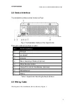
Page 11: ... SuperCombi Each part is defined as shown in table 1 No Function definition PV Input AC IN OUT Indicator Black Sampling of Battery Optional White Remote Control Charge Port 2A for Start Battery Optional Manual Switch Battery Table 1 SuperCombi Mounting Surface Definition 2 3 Wiring Cabin The diagram of the installation cabin is shown as Figure 3 ...

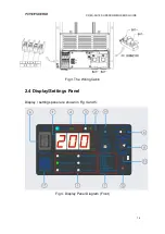
Page 12: ...CF M 3K 12 SUPERCOMBI USER S GUIDE 12 Fig 3 The Wiring Cabin 2 4 Display Settings Panel Display settings panel are shown in Fig 4 and 5 Fig 4 Display Panel Diagram Front ...

Page 13: ...arge 2 Parameter Unit 11 PageDown Buzzer sound off 3 PV Indicator 12 On Off 4 Working Indicator 13 Buzzer 5 Parameter Value 14 Remote 6 Rocker Switch On Off Energy Save 15 Reserved 7 Battery Type Selector 16 Reserved 8 AC Grid Current Selector 17 QR Code For Help 9 Charge Current Selector Table 2 Display Panel Surface Definition ...

Page 14: ...ith following roles Dry The inverter must be installed in a dry low moisture environment Temperature The full load working temperature is between 20 50 Safety Do not place it near by the fire inflammable fuel generator equipment Ventilation Install the inverter with at least 30mm ventilation space without obstruction at the top and bottom so that the heat inside the product can be ventilated by ai...

Page 15: ...CF M 3K 12 SUPERCOMBI USER S GUIDE 15 Fig 7 Super Combi Installation Space Diagram 3 2 System Wiring Diagram Fig 8 System Connection Diagram ...

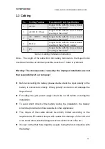
Page 16: ...possible Less than 1 meter is preferred Warning The consequences caused by the improper installation are not the responsibility of our company Before connecting the battery please double check the input polarity of the battery is connected correctly Wrong polarity connection will damage the SuperCombi For safety the grid power supply should be cut off before or during the installation To avoid sho...

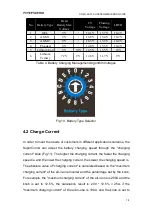
Page 17: ...damage caused by the mismatch of charging current battery damage is not within our responsibility 4 Basic Settings Note Before setting make sure that the Rocker Switch is in the center off position as shown in the following figure Otherwise it will damage the battery Fig 9 Turn off the Rocker Switch 4 1 Battery Type According to the type of battery installed the customers need to select the corres...

Page 18: ... customers in different application scenarios the SuperCombi can adjust the battery charging speed through the charging current knob Fig 11 The higher the charging current the faster the charging speed is and the lower the charging current the slower the charging speed is The absolute value of charging current is calculated based on the maximum charging current of the all in one inverter and the p...

Page 19: ...ry manufacturer Fig 11 Charge Current Selector 4 3 Grid Limit In order to adapt to customers different power supply availability customers can use the Grid Limit knob see Figure 9 to set the max current which the SuperCombi can get from the grid According to the value the SuperCombi can make full use of the power from the grid and also can prevent the grid supply being overloaded This parameter is...

Page 20: ...e rear of the remote panel See Figure 13 1 When the Auto Invert function is enabled the SuperCombi will output AC power automatically when the SuperCombi is disconnected from the Grid 2 When the Auto Invert function is disabled the SuperCombi will not output AC power if the SuperCombi is disconnected with the grid and it will enter Standby state Fig 13 Auto Invert Selector ...

Page 21: ...to Invert settings 1 When Auto Invert function is enabled the SuperCombi will output AC power to Short Break connection unless the Rocker Switch stays on the center position The status indicator on the remote control panel will turn green see Appendices and AC power will be drawn from the battery 2 When Auto Invert function is disable the SuperCombi will enter into Standby mode The indicator will ...

Page 22: ...rn blue see Appendices If the customer presses the On Offbutton for 3 seconds when charging the SuperCombi will stop charging The SuperCombi will continue to provide AC power to AC Output1 2 The status indicator will turn flashing blue see Appendices If the customer presses on off button for 3 seconds again the SuperCombi will enter into charge mode If the Charge Pro function added more features c...

Page 23: ...the power consumption the SuperCombi will enter into sleep mode automatically when the standby mode last for 5 minutes All the light of the digital cube and LED will turn off The panel can be woken up by pressing any button Under Sleep Mode if PV panel is connected and the PV voltage reaches the working threshold the internal MPPT model of SuperCombi will start to charge the battery without waking...

Page 24: ...operly under Emergency Mode we strongly recommend the customer to contact the supplier to repair the control panel or cable as soon as possible 6 Special Functions 6 1 Dual AC outputs The SuperCombi provides two AC outputs Power and Short Break The users can choose different output to provide AC power depending on load and needs Those loads need continuous AC power should be connected to Short Bre...

Page 25: ...onnected The SuperCombi will work in inverter mode to supply AC power to Short Break port So the port of Short Break can always output AC power no matter whether the grid is connected or not 6 2 Charge Pro Function The SuperCombi can simultaneously charge the battery and provide DC power to the DC load The DC load has the priority to get the power The current charged to the battery will be dynamic...

Page 26: ...is set to be 9A if the total AC load is 7A the current to be charged to the battery will be 2A no matter how much charge current is set Similarly if the charge current is set to 200A and DC load is 120A then the charge current to the battery will be 80A 6 4 On Grid Supply By using the On Grid Supply function when the power of grid supply is not sufficient for the load the SuperCombi will invert to...

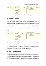
Page 27: ...hat the mains circuit breaker will not open Fig 20 Separate Supply Function Example Take Fig 20 as an example the Max Grid Current Limit is set to be 9A If the total AC load is 13A since the Separate Supply function the relay will turn off and the Grid will provide 6A to Power end and the SuperCombi will work as an inverter to provide another 7A to the Short Break end 6 6 Wire Compensation The lar...

Page 28: ...ompensate for the voltage drop on the battery connection line and increase the available capacity of batteries based on safety This function is particularly significant for the scenario when the battery cable is long For details of the optional function see section 2 2 Device Interface 6 7 Battery Capacity Testing Under the premise of using the function of Charge Pro and Wire Compensation the Supe...

Page 29: ...rature Compensation The rated voltage of lead acid battery is varied by temperatures To maximize the capacity and the safety of the battery the SuperCombi will compensate the battery voltage based on the battery s ambient temperature If the user chooses the hardware temperature compensation function the user will need to install the temperature detection device attached to the SuperCombi with the ...

Page 30: ...ccording to a unique charging software algorithm Warning Please make sure the low voltage dead battery is undamaged and rechargeable Any accidental loss conducted by misusing this function is not within the scope of our responsibility Please closely monitor the battery closely during charging ...

Page 31: ...er Output Waveform 5 Normal Frequency 50 60 Hz 0 3 Settable Efficiency Peak 91 Short Circuit Protection Yes INV AC Output 14A Max Charger Mode AC Input Nominal Voltage Range CF M 3K 12 A 220VAC 20 CF M 3K 12 B 230VAC 20 CF M 3K 12 C 240VAC 20 Frequency Range 50 60Hz 3Hz AC Nominal Current 14A Efficiency Full Load 91 AC Input Current Max 30A Max Power Factor 0 98 Full Load DC Output Current Range 0...

Page 32: ...ting 51 60 60W per Storage 40 70 Working Humidity Range 10 95 RH Non Condensing Safety EMC Safety EMC Safety Standards UL60950 IEC 62477 1 IEC 60335 2 29 EMC Standards CISPR 25 EN55014 EN61000 3 2 3 3 4 2 3 4 5 6 8 11 E mark ECE R10 V5 ISO7637 2 Control Dimension Control Dimensio n Remote Control CAN RS485 Cooling Temperature load controlled cooling fan Dimension W H D 271 82 391mm Packing Weight ...

Page 33: ...attery side is reasonable 3 Fasten the battery wiring 03 Battery over voltage Mismatched battery Check if the battery is in the specification range 04 Short circuit of battery side Dead battery or short circuit of batter side 1 Confirm that the battery is dead and use the dead battery charging function 2 Check if there is a short circuit on the wiring of battery side 21 Grid Under Voltage The Grid...

Page 34: ...ification range 1 Improve the Ventilation 2 Decrease the output power and ambient temperature 3 Check that the air vents of the All in One machines are not blocked 33 Fan fail Fan blocked or invalid 1 Check whether the fan of the All in One machine is stuck by foreign matter 2 Contact the distributor to return to the factory and replace the fan 34 Internal malfunction Internal abnormal of All in O...

Page 35: ...CF M 3K 12 SUPERCOMBI USER S GUIDE 35 temperature too high over temperature scheme 44 MPPT internal malfunction MPPT internal error Contact the distributors to return to the factory for inspection ...

Page 36: ...f button was pressed Charging stopped and AC output is on AC power comes from the grid Solid Stand by mode Auto invert was turned off Flash Fault happened Please read the fault number parameter screen and refer to chapter 9 Troubleshooting for details PV Indicator Solid The battery is fully charged by PV power Flash PV power is charging battery inverting providing DC power ...

Page 37: ...te purchased PowerPlus Australia Group Pty Ltd will take full responsibility to the product Please be care that if the product is damaged because of improper installation immersion foreign matter invasion or any malfunction caused by users PowerPlus Australia Group Pty Ltd will not take the responsibility for it ...

Page 38: ...na 518108 Tel 86 755 8652 9986 Email info powerscience net Australia Branch Add 5 17 25 Kinder St Campbellfield VIC 3131 Tel 61 416 766 688 Email au powerscience net European Representative Office Add An der Feuerwache 9 41836 Hückelhoven Germany Tel 49 2433 94018 0 Fax 49 2433 94018 99 Email eu powerscience net ...

Reviews: