Pg8
FOLDING RETRACTABLE STAIRWAY
To suit Hitachi EX3600 Excavator
Section 3
Operating Procedure
EX3600-FRS 3-8-15
To Lower Stairway (from the machine)
Position excavator in a level, safe area, away from the work face, whenever possible.
Position the excavator body square to the tracks, lower bucket, apply park brake and
lower engine speed to idle.
Descend stairway behind cabin to lower walkway.
Check that the area below and behind the Folding Raising Stairway (FRS) is clear of
people and obstacles, and lower stairway by operating the two position electrical switch
adjacent to the stairway, to the down position by pressing the switch down.
Hold the switch in the down position until stairway is fully extended and lowered.
If the excavator is parked on uneven ground, the bottom of the stairway may touch the
ground before the FRS is in the fully extended and lowered position.
Should this occur, descend the stairway with caution.
Bottom of stairway is designed to rest on the ground in the fully lowered and extended
position, but can be used in the fully lowered position without resting on the ground.
To Raise Stairway
Ascend the stairway onto the lower walkway of the excavator
Ensure the area around the stairway is clear of people and standing to the side, clear of
the area the handrails and stairway raises into, operate the electrical switch to the raise
position (up).
Hold the switch in the up position until the stairway is in the fully raised position.
The stairway is now raised and stored.
Note:
The stairway is interlocked with the swing interlock of the excavator, and the machine will
not swing with the stairway out of the fully raised position.
Operation of the FRS mechanically extends the lower stair section as the stairway is
lowered by means of the link rods to the upper platform of the FRS.
There is no method of individual control of the upper and lower sections.
OPERATING NOTES
NOTE:
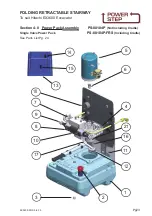
FLOW CONTROL VALVE ADJUSTMENT:
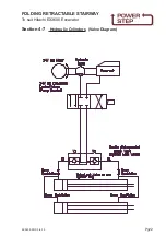
The valve should be positioned to restrict the flow and speed of the Power Step when
lowering. Adjust the knob on top of the valve by turning left or right (clockwise) when the
step is being lowered, until it is lowering at a safe and reasonable speed.
When it is adjusted, lock the adjusting knob by tightening the grub screw located on the
side of the knob.
NOTE:
MAGNETIC 'GO' SWITCH ADJUSTMENT:
The switch target trigger area is located on the opposite side and end from the cable entry
point on the switch. Once it is mounted to the switch bracket, adjust the switch in or out
from the stair steel trigger point, to be within 3mm - 10mm from touching each other when
the stair is in the desired rest position.
[DO NOT EXCEED 10mm DISTANCE BETWEEN THE SWITCH AND STRIKER PLATE].
Test by raising and lowering the Power Step a couple of times and adjust again if
necessary.


