20
4111-0044 — June 2021
© 2021 Systems, LLC
8. Fully close the down speed flow control valve
by turning clockwise. Then, set the down speed flow
control valve by incrementally opening the valve until
the leveler takes 15-20 seconds to descend from
stored to full below dock position.
9. Once ideal down speed flow control setting is
achieved, lock the adjustment in place by tightening
the set screw (
C
) on the adjustment knob.
10. Raise the maintenance props to the stored
position and tighten all hardware with wrench.
11. Lower the leveler to a 45 degree angle.
12. Cycle lip by pressing the LOWER and LIP
buttons together to lower the lip, then press the
RAISE and LIP buttons together to raise the lip. Lip
cylinder is now purged.
13.
Raise leveler to stored position and top off
hydraulic fluid as required.
1. Using an external lifting device, support the RCR
leveler in the stored position, with the maintenance
props lowered in the maintenance position and all
hardware tightened by wrench.
2. Lock-out and tag-out the leveler.
3. New equipment only: Remove shipping bands
from hoist cylinder(s).
4. New equipment only: Fill powerpack fluid
reservoir with hydraulic fluid. See page 28 for
acceptable fluid specifications.
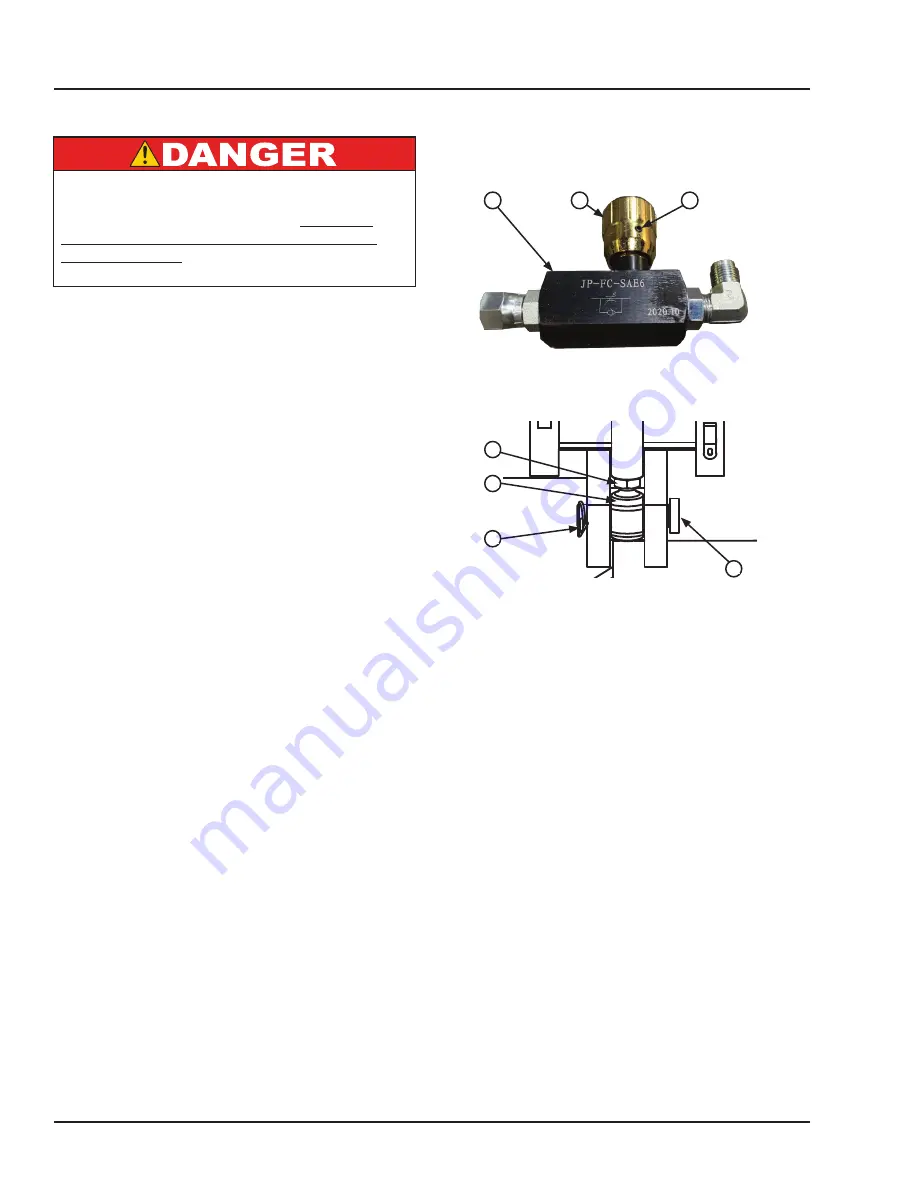
5. Fully open the down speed flow control valve (
A
)
by turning knob (
B
) counter-clockwise (see Figure
19). Loosen set screw (
C
) to turn knob. Flow control
valve location varies depending on options; see
Component Identification on pages 9-11 for location
or contact Technical Services.
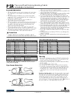
6. With the cylinder pin(s) (
F
) removed from the
embed/carriage, restore power to the dock leveler.
Then cycle the hoist cylinder(s) up and down at least
six times using the leveler’s own hydraulic power.
Ensure the cylinder rod(s) smoothly extend/retract.
7. Reconnect the hoist cylinder yoke(s) to the base
of the embed or carriage by completing the following
steps (see Figure 20):
a. Fully extend the hoist cylinder by pressing
and holding the RAISE button until the rod stops
extending and the powerpack goes into pressure
relief.
b. Using the external lifting device, position the
leveler platform so that it is leaning 4 degrees
towards the inside of the building/dock.
c. With the platform leaning 4 degrees towards
inside, loosen the jam nut (
D
) and adjust the
yoke (
E
) so that the cylinder pin (
F
) easily slides
through both the trunnion and yoke.
d. Install and lock rue clip (
G
) into place.
A— Flow Control Valve
B— Adjusting Knob
C— Set Screw
D— Jam Nut
E— Yoke
F— Hoist Cylinder Pin
G— Rue Clip
INSTALLATION
Purging Air From RCR Hydraulic System & Adjusting Yoke
If the equipment being serviced is a new start-
up, opened to atmosphere, or lifted manually, air
will enter into the hydraulic system. Whenever
this happens, air must be fully purged from the
hydraulic system.
Failure to do so will result in
death or serious injury.
TOLERANCES
(UNLESS OTHERWISE NOTED)
FRACTIONAL:
1/32"
DECIMAL:
.00 =
.01"
.000 =
.005"
ANGULAR:
1
MATERIAL
DRAWN BY
CHECKED BY
DRAWING NO.
DATE
johnschlintz
1/27/2020
VS-VSH
PARTS
EXPLODED
VIEW PG 40
2021
P O W E R A M P
M C G U I R E
D L M
S
S Y
Y S
S T
T E
E M
M S
S
L o a d i n g D o c k E q u i p m e n t
This print is the property of Systems, LLC and represents a proprietary article in which Systems, LLC retains any and all
patent and other rights, including exclusive rights of use and/or manufacture and/or sale. Possession of this print does
not convey any permission to reproduce, print or manufacture the article or articles shown therein, such permission to be
granted only by written authorization signed by an officer or other authorized agent of Systems, LLC thereof.
STOCK NO.
REV A - ECN 18-066
C
B
A
Figure 19
Figure 20
F
D
E
G
Summary of Contents for RCR Series
Page 25: ...23 4111 0044 June 2021 2021 Systems LLC OPERATION This page intentionally left blank ...
Page 38: ...36 4111 0044 June 2021 2021 Systems LLC PARTS Platform Hydraulic Hoses C A G F E D B H ...
Page 58: ...56 4111 0044 June 2021 2021 Systems LLC This page intentionally left blank MISCELLANEOUS ...


