14
4111-0008 — April 2017
June 2017
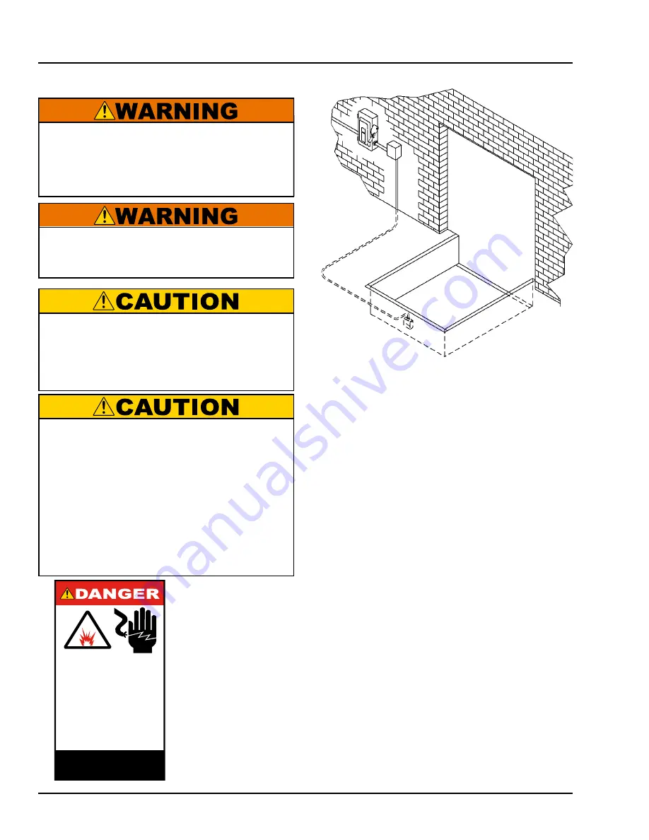
1. Mount the push button control panel (B) so bottom
of control panel-to-dock floor distance (C) is 48 in.
(1219.2 mm).
2. Install electrical disconnect panel (A) if not already
installed.
3. Install and connect the control wiring.
4. Connect the dock leveler power cable to the field
wires in the pit junction box. Refer to the electrical
drawings supplied with the dock leveler.
INSTALLATION
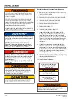
Install Control Panel and Wiring
B
A
C
D
The electrical power must be OFF prior to electrical
installation. For maximum protection, use an OSHA
approved locking device to lock out all power
sources. Only the person installing the equipment
should have the key to unlock the power source.
DO NOT make any final electrical connections until
all welding has been completed.
All electrical work — including the installation of
the disconnect panel, control panel, and final
connections to the pit junction box — must be
performed by a certified electrician and conform to
all local and applicable national codes.
When drilling access hole in the control box, DO NOT
penetrate too deep, components may be damaged.
DO NOT turn control upside down to drill any access
holes. To prevent damaged to electrical components
from debris cover components prior to drilling
Seal all conduit entrances to prevent moisture from
entering the control box.
DO NOT use compressed air to clean control box.
Recommended to vacuum debris from inside.
1.50"
3.00"
Decal Size: 1.5 x 3
File Name: 1751-0736 Rev A
Arc Flash and
Shock Hazard
PPE [Personal Protection
Equipment] Required
De-energize equipment before
working on or inside. Do not
open cover without appropriate
PPE. Refer to NFPA 70E for
PPE requirements. This panel
may contain more than one
power source.
Hazardous Voltage
Will Result in Death
or Serious Injury
1751-0736 Rev A
A— Disconnect Panel
B— Control Panel
D— Placard
(provided by others)
C— Distance, 48 in. (1219.2 mm)
* Refer to OSHA regulation 1910.146. Confine Space
* Refer to OSHA regulation 1910.147. Lockout/Tagout
Summary of Contents for VS series
Page 44: ...42 4111 0008 April 2017 June 2017 Centra Power Hydraulic Components PARTS A B E D F G I H C ...
Page 47: ...45 4111 0008 April 2017 June 2017 This page was left intentional left blank PARTS ...
Page 53: ...51 4111 0008 April 2017 June 2017 PARTS This page was left intentional left blank ...


