17
4111-0008 — April 2017
June 2017
INSTALLATION
Rod Eye adjustment & New installation
1. Support the leveler with the maintenance props.
Lock out the storage prop with the prop pin and
clip.
2. Lock-out and tag-out the leveler.
3. Remove lower hoist cylinder mounting pin.
4. Remove one of two screws holding the stored
limit switch. Swivel stored limit switch away from
storage prop.
5. Restore power to the leveler. Confirm the BLUE
stored indicator light is no longer illuminated.
6. Cycle the hoist cylinder up and down at least
once to make cylinder is fully extended.
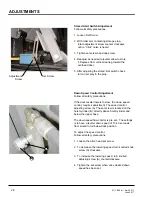
7. Rod eye should be adjusted so the center of the
rod eye is half way below the center of the hole
of the embed. After adjusted tighten jam nut.
8. To center the rod eye with the embed tap the
lower button until the pin (lube pin) can be
installed. Use washers to keep the rod eye
centered in the opening.
9. After pin has been installed, store maintenance
props and prop pin and clip, test the leveler for
operation.
Purging Air From The VS Hydraulic
System.
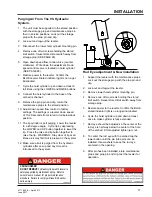
1. The unit must be supported in the stored position
with the storage prop and maintenance props in
their in service positions. Lock out the storage
prop with the prop pin and clip.
2. Lock-out and tag-out the leveler.
3. Disconnect the lower hoist cylinder mounting pin.
4. Remove one of two screws holding the stored
limit switch. Swivel stored limit switch away from
storage prop (SEE PAGE 28).
5. Open down speed flow control valve (counter
clockwise). Write down the adjustment. Down
speed control valve is located on hoist cylinder
(SEE PAGE 28).
6. Restore power to the leveler. Confirm the
BLUE Leveler Stored indicator light is no longer
illuminated.
7. Cycle the hoist cylinder up and down at least 6
full times using the LOWER and RAISE buttons.
8. Connect the hoist cylinder to the base of the
embed is channel.
9. Remove the prop pin and clip, return the
maintenance props to the stored position.
10. Adjust down speed flow control to factory
settings. The settings is a leveler down speed
of 15-20 seconds from stored to full below dock
position.
11. The lip cylinder is self purging. Lower the leveler
to a 45 degree angle. Cycle lip by depressing
the LOWER and LIP button together to lower the
lip. Press the raise and lip button together to
raise the lip. WARNING: Stay clear of lip at all
times as it may fall if air is present in the system.
12. Make sure all air is purged from the hydraulic
cylinders after set-up and any time air is
introduced to the system.
File Name: 1751-0138 Rev B
Decal Size: 4 x 2
CRUSH HAZARD
DO NOT REMOVE
hydraulic cylinder until leveler is
safely supported by maintenance prop. Refer to
owner’s/user’s manual for proper maintenance
procedure. Failure to comply will result in death or
serious injury.
1751-0138 Rev B
File Name: 1751-0229 Rev E
Decal Size: 4 x 1
Summary of Contents for VS series
Page 44: ...42 4111 0008 April 2017 June 2017 Centra Power Hydraulic Components PARTS A B E D F G I H C ...
Page 47: ...45 4111 0008 April 2017 June 2017 This page was left intentional left blank PARTS ...
Page 53: ...51 4111 0008 April 2017 June 2017 PARTS This page was left intentional left blank ...


