background image


11

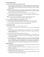
3-5. Single UPS Operation 

1. Turn on the UPS with utility power supply (in AC mode)   

1)    After power supply is connected correctly, set the breaker of the battery pack at “ON” position (the 

step only available for long-time model). Then set the input breaker at “ON” position. At this time 
the fan is running and the UPS supplies power to the loads via the bypass. The UPS is operating 
in Bypass mode.   

NOTE: 

When UPS is in Bypass mode, the output voltage will directly power from utility after you switch 

on the input breaker. In Bypass mode, the load is not protected by UPS. To protect your precious 
devices, you should turn on the UPS. Refer to next step.   

2)    Press and hold the “ON” button for 0.5s to turn on the UPS and the buzzer will beep once.     

3)  A few seconds later, the UPS will enter to AC mode. If the utility power is abnormal, the UPS will 

operate in Battery mode without interruption. 

NOTE:  

When the UPS is running out battery, it will shut down automatically at Battery mode.   

When the utility power is restored, the UPS will auto restart in AC mode.   

2. Turn on the UPS without utility power supply (in Battery mode) 

1)    Make sure that the breaker of the battery pack is at “ON” position (only for long-time model).   

2)    Press and hold the “ON” button for 0.5s to turn on the UPS, and the buzzer will beep once. 

3)    A few seconds later, the UPS will be turned on and enter to Battery mode. 

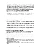
3. Connect devices to UPS 

After the UPS is turned on, you can connect devices to the UPS. 

1)    Turn on the UPS first and then switch on the devices one by one, the LCD panel will display total 

load level.   

2)    If it is necessary to connect the inductive loads such as a printer, the in-rush current should be 

calculated carefully to see if it meets the capacity of the UPS, because the power consumption of 
this kind of loads is too big. 

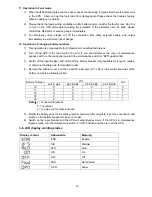
3)    If the UPS is overload, the buzzer will beep twice every second. 

4)    When the UPS is overload, please remove some loads immediately. It is recommended to have 

the total loads connected to the UPS less than 80% of its nominal power capacity to prevent 
overload for system safety.   

5)    If the overload time is over acceptable time listed in spec at AC mode, the UPS will automatically 

transfer to Bypass mode.    After the overload is removed, it will return to AC mode. If the overload 
time is over acceptable time listed in spec at Battery mode, the UPS will become fault status. At 
this time, if bypass is enabled, the UPS will power to the load via bypass. If bypass function is 
disabled or the input power is not within bypass acceptable range, it will cut off output directly. 

4. Charge the batteries 

1)    After the UPS is connected to the utility power, the charger will charge the batteries automatically 

except in Battery mode or during battery self-test.   

2)  Suggest to charge batteries at least 10 hours before use. Otherwise, the backup time may be 

shorter than expected time. 

3)    Make sure the battery numbers setting on the control board (Please refer to the section 3-4-12 for 

detailed setting) is consistent to real connection. 

4)    The charging current can be changed from 0.5A to 6A via LCD or software. Please make sure that 

the charging current is suitable to battery specification.


Summary of Contents for KNIGHT ONLINE SERIES

Page 1: ...USER S MANUAL KNIGHT ONLINE SERIES UPS 220V 1000 L 2000 L 3000 L Uninterruptible Power Supply System...

Page 2: ...E UPS INSTALLATION 5 2 3 SOFTWARE INSTALLATION 7 3 OPERATIONS 8 3 1 LCD PANEL 8 3 2 BUTTON OPERATION 8 3 3 LED INDICATORS AND LCD PANEL 10 3 4 AUDIBLE ALARM 110 3 5 SINGLE UPS OEPRATION 131 3 6 LCD DI...

Page 3: ...em Do not connect domestic appliances such as hair dryers to UPS output sockets The UPS can be operated by any individuals with no previous experience Connect the UPS system only to an earthed shockpr...

Page 4: ...must be kept well away from the batteries Caution risk of electric shock The battery circuit is not isolated from the input voltage Hazardous voltages may occur between the battery terminals and the...

Page 5: ...re use NOTE There are two different types of online UPS standard and long time models Please refer to the following model table Model Type Model Type 6K R 6K R L 10K R Standard 10K R L Long time 2 1 R...

Page 6: ...ordance with the local electric laws regulations and execute the following instructions by professional personnel 1 Make sure the mains wire and breakers in the building are in compliance with the sta...

Page 7: ...k cover back to the rear panel of the UPS Warning Only for standard model Make sure the UPS is not turned on before installation The UPS should not be turned on during wiring connection Do not try to...

Page 8: ...Wrong connection may cause permanent damage of the UPS Make sure the protective earth ground wiring is correct The current spec color position connection and conductance reliability of wire should be...

Page 9: ...n to return to last menu in setting menu Test Up Button Battery test Press and hold the button more than 2s to test the battery while in AC mode or CVCF mode converter mode UP key Press this button to...

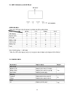
Page 10: ...e frequency battery voltage load information and internal temperature V input output voltage battery voltage Hz frequency load level C temperature KW active power KVA apparent power A output current M...

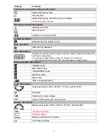
Page 11: ...ote LED lighting LED faded When the UPS under bypass mode but no bypass output voltage exists Bypass LED will flicker 3 4 Audible Alarm Description Buzzer status Muted UPS status Bypass mode Beeping o...

Page 12: ...en switch on the devices one by one the LCD panel will display total load level 2 If it is necessary to connect the inductive loads such as a printer the in rush current should be calculated carefully...

Page 13: ...through monitoring software 7 Turn off the UPS with utility power supply in AC mode 1 Turn off the inverter of the UPS by pressing OFF button for at least 0 5s and then the buzzer will beep once The...

Page 14: ...intenance bypass switch on the rear panel and turn the maintenance switch to BPS position first 3 Switch off the input breaker and switch off the battery breaker only available for long run model or d...

Page 15: ...or down key to select the displayed information 1 Output Voltage 2 Output Frequency 3 Input Voltage 4 Input Frequency 5 Battery Voltage 6 Load Level 7 Output Current 8 Output Apparent Power 9 Output A...

Page 16: ...eptable high frequency for bypass mode Y 08 Bypass mode forbidden allowed Y 09 Manual bypass mode enable disable Y 10 Battery backup time setting Y Y Y Y Y 11 Hot standby function enable disable Y Y Y...

Page 17: ...y mode when input frequency is not within 56 64 Hz 03 Output frequency setting Interface Setting Parameter 2 Output Frequency 50 0Hz output frequency is setting for 50 0Hz 60 0Hz output frequency is s...

Page 18: ...USER S MANUAL KNIGHT ONLINE SERIES UPS 220V 6000 L 10000 L Uninterruptible Power Supply System...

Page 19: ...ot allowed for running in Bypass mode under any situations OPN Bypass allowed When selected UPS will run at Bypass mode depending on the setting of Manual Bypass enable disable 09 Manual bypass enable...

Page 20: ...erface Setting Parameter 2 Voltage range is from 9 9V to 9 9V and the default value is 0V NOTE Before making voltage adjustment be sure to disconnect all batteries first to get the accurate charger vo...

Page 21: ...s 1 group These parameters are for the battery backup time calculation 17 Backup time calibration Interface Setting Parameter 2 Calibrate the displayed backup time by adjusting this multiplier factor...

Page 22: ...ry Test This operation is used to check the battery status Bypass mode When input voltage is within acceptable range and bypass is enabled turn off the UPS and it will enter Bypass mode Alarm beeps ev...

Page 23: ...in the end of life 1 Recharge the battery 2 Correct the battery number 3 Replace the battery Warning 09 Overload Remove excess loads from UPS output Warning 0A 1 Fan is blocked 2 Fan is in the end of...

Page 24: ...ppens again If the problem still persists please contact the dealer for repair 2 Contact the dealer for repair Fault 03 The internal converter fails so the DC bus voltage is too low Contact the dealer...

Page 25: ...There is some error in the parallel system Contact the dealer for repair Fault 41 The internal temperature is too high and reaches the fault level shutdown point 1 Maybe the environment is hot 2 Mayb...

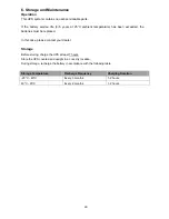
Page 26: ...atteries must be replaced In this case please contact your dealer Storage Before storing charge the UPS at least 7 hours Store the UPS covered and upright in a cool dry location During storage recharg...

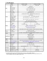
Page 27: ...ode and to 90 when the output voltage is adjusted to 208VAC If the UPS is installed or used in a place where the altitude is above than 1000m the output power must be derated one percent per 100m Prod...

Page 28: ...allation and setup 3 2 1 Rear panel view 3 2 2 Setup the UPS 3 3 Operations 5 3 1 LCD Panel 5 3 2 Button Operation 5 3 3 Audible Alarm 7 3 4 LCD display wordings index 7 3 5 UPS Setting 7 3 6 Operatin...

Page 29: ...em Do not connect domestic appliances such as hair dryers to UPS output sockets The UPS can be operated by any individuals with no previous experience Connect the UPS system only to an earthed shockpr...

Page 30: ...must be kept well away from the batteries Caution risk of electric shock The battery circuit is not isolated from the input voltage Hazardous voltages may occur between the battery terminals and the...

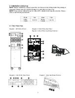
Page 31: ...for L model 7 Output receptacles 8 Output circuit breaker 9 Output terminal 2 2 Setup the UPS Step 1 UPS input connection Plug the UPS into a two pole three wire grounded receptacle only Avoid using...

Page 32: ...r PC With the monitoring software installed you can schedule UPS shutdown start up and monitor UPS status through PC The UPS is equipped with intelligent slot perfect for either SNMP or AS400 card Whe...

Page 33: ...Up key Press this button to display previous selection in UPS setting mode Switch to UPS self test mode Press and hold ON Mute button for 5 seconds to enter UPS self testing while in AC mode ECO mode...

Page 34: ...e frequency battery voltage load information and internal temperature V input output voltage battery voltage Hz frequency load level C temperature KW active power KVA apparent power A output current M...

Page 35: ...ameters to set up the UPS Parameter 1 For program alternatives Parameter 2 Option setting or values for each program 01 Output voltage setting Interface Setting For 200 208 220 230 240 VAC models O P...

Page 36: ...from 85Vac to 115Vac Default 85Vac 05 Acceptable high voltage setting in Bypass mode Interface Setting Press Down key or Up key to set the acceptable high voltage point HLS in bypass mode For 200 208...

Page 37: ...ptable low voltage setting in ECO mode Interface Setting Press the Down key or Up key to set acceptable low voltage point LLS in ECO mode For 200 208 220 230 240 VAC models setting range is from 7V to...

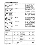
Page 38: ...disabled Default 00 Exit setting 3 6 Operating Mode Description LCD display Operating mode Description Standby mode UPS power off and no output supply power but still can charge battery Online mode I...

Page 39: ...s mode can be set up by the front panel Alarm is sounding every 10 second Fault mode While a fault has occurred the ERROR icon and the fault code will be displayed 3 7 Faults Reference Code Fault even...

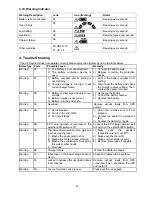
Page 40: ...not connected or Battery Replace Sounding every second Over Charge Sounding every second Over temperature Sounding every second Charger failure Sounding every second Battery fault Sounding every secon...

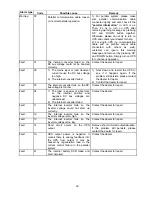
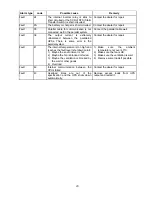
Page 41: ...mains Remove excess loads from UPS output first Then shut down the UPS then restart it Fault code is shown as 43 and The icon is lighting on LCD display and alarm is continuously sounding UPS shut dow...

Page 42: ...aler Storage Before storing charge the UPS 5 hours Store the UPS covered and upright in a cool dry location During storage recharge the battery in accordance with the following table Storage Temperatu...

Page 43: ...15 6 Specifications Derate capacity to 60 of capacity in Frequency converter mode and to 80 when the output voltage is adjusted to 208VAC...

Reviews: