background image

To keep your PowerBass Electronic Crossover running at top performance, choosing the proper location is of 
utmost importance. The crossover should also be protected from exposure to moisture and direct sunlight.

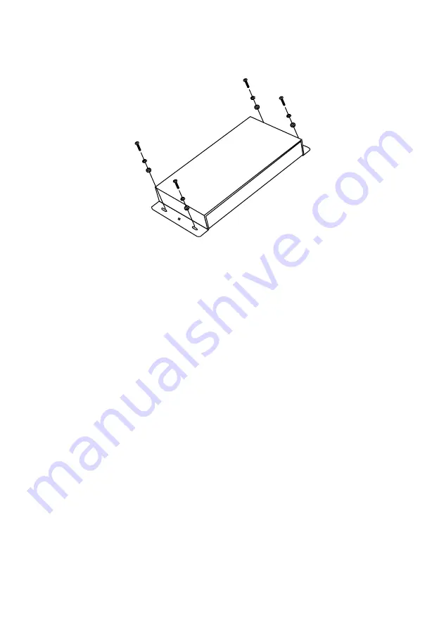
The best place to mount your crossover is a convenient location which will allow access to the inputs and other 
variable controls.  Be sure that the power and signal cable connections can enter and leave the crossover in a 
straight line to avoid the risk of kinked wires causing malfunction.

You may use the crossover as a template and mark the four screw locations with a felt tip pen.  Use caution 
to make sure there are no objects behind the installation surface that may become damaged during drilling.

Power Wiring and Signal Connections

The potential of your XEX-23 crossover is unlimited. When mated with our PowerBass amplifiers, subwoofers 
and separates the XEX-23 can deliver sonic reproduction that rivals a live performance. The following pages 
give just a few examples of popular system configurations; however you are not limited to just these. For 
more exotic system layouts, consult with your local PvowerBass Xtreme dealer.
Be extra careful when routing your RCA audio interconnect cables. Car environments are notorious for poorly 
insulated wires. This means that hiss, engine noise, and fan noise can easily be picked up through RCA 
cables if run incorrectly.
Make sure that the cables for power and audio signal are not on the same side of the vehicle and that they 
do no cross each other; this will help reduce any noise that may radiate from the power cable and the signal 
cable.  If an audio cable is too close to a power cable, it may pick up the magnetic field generated by the 
power cable, which could lead to a loss of quality in your signal.

If RCA interconnects must cross power cables, noise can best be avoided by crossing them 
between 45° and 75°.

MOUNTING THE


CROSSOVER

9

Summary of Contents for Xtreme XEX-23

Page 1: ...ROSSOVER Owners Manual Please read through this manual to familiarize yourself with your new crossover Should your PowerBass Xtreme processor ever require service you will need to have the original da...

Page 2: ......

Page 3: ...23 3 Way Electronic Crossover Designed and engineered using the latest in signal processing technol ogy virtually any car stereo system will benefit from the addition of this unique and versatile prod...

Page 4: ...rcuitry The PowerBass XEX 23 takes the incoming audio signals and separates them into three distinct frequency ranges according to the frequency range of the speakers that are going to be amplified Th...

Page 5: ...ve terminal of the vehicle battery or other constant 12V sources 2 REMOTE Remote Turn On Input Terminals To be connected to the remote control wire or antenna lead of the head unit for turn ON OFF 3 G...

Page 6: ...no subwoofer output s this switch should be at the FRONT position to allow the signal from the front rear channels supply to the subwoofer input selection of the crossover 9 SUBWOOFER LINE IN RCA JACK...

Page 7: ...ss amplifier inputs considered to the Band Pass switch 20 PHASE Inverter Switch Positioning the switch to the 0 degree the subwoofer output signal in phase with the front rear output signals to the 18...

Page 8: ...ejection 2 Bolt the crossover to the mounting surface and make sure the mounting screws do not touch any metal part of the vehicle to ensure maximum noise rejection 3 Using the Power Plug provided con...

Page 9: ...oofers and separates the XEX 23 can deliver sonic reproduction that rivals a live performance The following pages give just a few examples of popular system configurations however you are not limited...

Page 10: ...gle ground location point where the amplifiers are also grounded Once you have completed wiring the Power Plug gently push it into the socket on the side panel of the PowerBass XEX 23 POWER CONNECTION...

Page 11: ...NT and the INPUT MODE switch to FRONT This will allow the signals to be fed internally to the SUBWOOFER and REAR sections to give proper results The FREQUENCY MULTIPLIER switch should be in the X1 pos...

Page 12: ...4 channel amp for FRONT and REAR mono amp for SUBWOOFER 5 channel amp IMPORTANT Correctly set the switches as shown in the diagrams below...

Page 13: ...ow the signals to be fed internally to the SUBWOOFER section to give proper outputs and set the INPUT MODE switch to FRONT REAR to allow the head unit to control the fader The FRE QUENCY MULTIPLIER sw...

Page 14: ...control from the source unit Set the INPUT MODE switch to the FRONT REAR position to allow the source unit to control fader Please Note Some source units offer independent control of the subwoofer non...

Page 15: ...ts The FREQUENCY MULTIPLIER switch multiplies the cross over frequencies by 10 so instead of crossing from 30 Hz to 500 Hz it will cross from 300 Hz to 5 kHz On the REAR section the FREQUENCY MULTIPLI...

Page 16: ...w pass the crossover should be in the maximum position For subwoofers the sub sonic filter may still be used if available Set the desired CROSSOVER FREQUENCY for the SUBWOOFER output using your LOW PA...

Page 17: ...UT Set the desired frequency cutoff using the HIGH PASS dial for your HIGH output such as tweeters The FREQUENCY MULTIPLIER switch must be set to X10 as most tweeters cannot safely operate at less tha...

Page 18: ...mplifiers ADJUSTING OVERALL BALANCE OF THE SYSTEM Once you complete the signal matching stage the following steps should be made to set the overall linearity of the system This may be necessary due to...

Page 19: ...mum crossover frequencies and output levels are located mark them down on the chart below for future reference in case the settings are accidentally changed Front Frequency Selector __________________...

Page 20: ...ol 3 Turn up the Input Gain controls 4 Check the Ground connections 5 Push the Source button Hiss 1 Turn down the amplifier gains 2 Adjust the Source unit output 3 Check for kinked or faulty RCA inter...

Page 21: ...igh Pass 30Hz 5kHz Rear High Pass Band Pass 30Hz 5kHz Subwoofer 30Hz 500Hz Input Voltage 6 Volts Maximum Output Voltage 10 Volts Supply Voltage 11 15 VDC Dimensions W x L x H 7 1 8 x 6 7 8 x 1 1 2 181...

Page 22: ...id damage or exposure to excessive heat Attempted repairs or alterations of any nature Product that has not been installed according to this owners manual Any implied warranties including warranties o...

Page 23: ...23...

Page 24: ...PowerBass Xtreme A division of PowerBass USA Inc 13936 Mountain Avenue Chino CA 91710 Tel 909 993 5399 Fax 909 993 5393 www powerbassusa com...

Reviews: