PowerBoss, Inc. Copyright 2010
Admiral 38C Scrubber PB# 4100055UM Rev.* 08/10
Page 78
Maintenance and Service
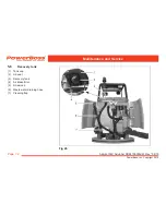
Removing the brush holder
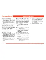
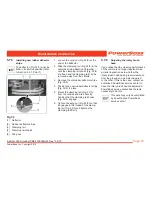
1. Slide the locking lever (Fig. 31/1) to the
middle of the device and hold it there.
2. Allow the brush holder (Fig. 31/6) to
lower under its own weight and then
pull out.
3. Release the locking lever (Fig. 31/1).
Disassembling the rotary brushes
Pull out the rotary brush (Fig. 31/5), over-
coming its resistance. Also refer to Section
2.3.1 (reverse working sequence).
Installing the rotary brushes
Refer to Section 2.3.1.
Mounting the brush holder
1. Slide the locking lever (Fig. 31/1) to the
middle of the device and hold it there.
2. Mount the brush holder (Fig. 31/6) on
the rotary brush, press against the
housing and then slide upwards as far
as possible.
3. Pivot the locking lever (Fig. 31/1) back
under the brush holder as far as pos-
sible.
5.7.3
Cleaning the contact surfaces
Each time the rotary brushes are changed,
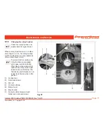
all the contact surfaces (Fig. 31/4 and Fig.
29/7) must be thoroughly cleaned with a
damp cloth, with a little cleaning agent
added, if necessary.
Also clean the small contact
surfaces!
5.7.4
Adjusting the locking lever for
the brush holder
1. Remove the brush holder (Fig. 31/6)
(refer to paragraph ”Removing the
brush holder”).
2. Loosen the counternut (Fig. 31/3).
3. Screw the oval-head screw (Fig. 31/2)
in or out.
4. Close the brush holder (refer to para-
graph ”Mounting the brush holder”) on
a trial basis.
The oval-head screw (Fig. 31/2)
is adjusted correctly when it
lightly scrapes under the brush
holder (Fig. 31/7).
5. Remove the brush holder (Fig. 31/6)
(refer to paragraph ”Removing the
brush holder”) and adjust the oval-
head screw (Fig. 31/2) until it is at the
correct height (repeat Step 4 several
times if necessary).
6. Tighten the counternut (Fig. 31/3).


