background image

Page 10

PowerBoss

®

2 First Operation

2.1 Instruction

Instruction is required before the fi rst 
operation. First instruction into handling 
of the machine must be held by a 
qualifi ed
person sent by your local PowerBoss 
dealer. Your PowerBoss dealer will 
be informed upon delivery of the unit 
and will contact you to make a date for 
instruction.

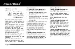
2.2 Initial Charging Procedure

Before fi rst operation of the 
machine, fully Charge the 
battery with an initial charging 
procedure and comply with the 
operating instructions of the
charger as well as with those 
of the battery manufacturer.
PowerBoss  cannot be held 
liable for damages resulting 
from the
fact that the initial charging 
has not or insuffi  ciently been 
done.

2.3 Before Operation Of Machine

Perform the following inspections before 
operation.
1. Check parking site for signs of leakage. 
Hoses, lines and tanks must be free from 
any leakage or damage.
2. Install brushes and squeegee, see
maintenance chapter.
3. Install batteries and connect battery 
cable, see maintenance chapter.
4. Check battery charge and proceed
to charging of batteries if required.
Generally proceed to initial charging
before fi rst operation of the machine.
5. Empty dirty water Recovery tank and 
clean it if required, see maintenance 
chapter.
6. Fill clean water tank and add  a cleaning 
agent according to the manufacturer’s 
recommendations. 

Use only cleaning agents suitable 
for automatic machines (low-
foaming type) and comply with 
the instructions for use. Follow 
directions for disposal and 
warning information as specifi ed 
by the manufacturer.

2.4 Start Machine

Before starting the machine, set the 
forward/reverse level to neutral position. If 
the lever is not in the neutral position when 
machine is switched on, an error message 
will occur. Use the following 
procedure reset the machine into operating 
mode:
• Disconnect main plug of the charger from 
outlet and fasten to the holder.
• Switch on the machine by turning the 
ignition key from position (0) to position (1).

2.5 Operation

1. Turn  on the machine via ignition switch.
2. Use hand lever (Fig. 5/3) to lower 
squeegee. Vacuum motor turns on 
automatically.
3. Switch on clean water supply by solution 
switch (Fig. 4/14).
4. Adjust clear water amount by means of 
metering switch (Fig. 4/13).
5. Use pedal (Fig. 5/9) to lower brush head.
6. Use forward/reverse lever (Fig. 5/1) to
adjust  speed and direction.
Increase the scrub brush pressure if
required with pedal (Fig. 5/10) .

Summary of Contents for Phoenix 26

Page 1: ...PowerBoss The Power of Clean PowerBoss Inc A member Of The Hako Group User Manual Phoenix 26 988026UMPB REV B 06 2022...

Page 2: ...al Please be advised explicitly that we cannot accept any legal issues out of the contents of this manual If repair work must be performed make sure that only genuine spare parts are used Genuine spar...

Page 3: ...nd brushes Damages caused by overload negligence and unauthorized modi cation of the machine are not covered by warranty Moreover any claim for warranty cannot be accepted if damages of the machine ar...

Page 4: ...ts 11 3 Operation 12 3 1 Method Of Operation 12 3 1 1 Scrub Head Assembly 12 3 1 2 Clean Water Tank 12 3 1 3 Squeegee 13 3 1 4 Dirty Water Recovery Tank 13 3 1 5 Drive System 13 3 1 6 Batteries and Ch...

Page 5: ...Tank 31 5 6 3 Clean Suction Filter 31 5 7 Scrub Head 32 5 7 1 Cleaning Brushes 32 5 7 2 Changing Brushes 32 5 7 3 Changing De ector Roller 32 5 7 4 Changing Scrub Head Skirt 32 5 8 Squeegee 33 5 8 1...

Page 6: ...e of the machine The operating instructions must be on hand at the place of machine use and therefore have to be kept readily available at the machine When selling or lending the machine for rent hand...

Page 7: ...e of persons within the operation area especially children Start moving immediately after brush head has lowered otherwise the brush might leave traces on the surface Lift the brush head before going...

Page 8: ...tive devices have been tted and positioned 1 5 Speci c Hazards Electric system Only use genuine fuses with the correct rating In case of malfunction of the electrical system immediately shutdown machi...

Page 9: ...ssing or illegible labels immediately PowerBoss Decal Fig 1 1 Machine identi cation number Fig 1 2 Dirty water drain hose Fig 1 3 A Read and observe the instruction manual Fig 1 2 B Maximum inclinatio...

Page 10: ...proceed to initial charging before rst operation of the machine 5 Empty dirty water Recovery tank and clean it if required see maintenance chapter 6 Fill clean water tank and add a cleaning agent acco...

Page 11: ...ve the legal directives and local regulations for disposal of detergents see Water Management Act 4 Check clean water lter 5 Check squeegee blades and suction hose 6 Check operation function and setti...

Page 12: ...the forward reverse lever is in the neutral position machine is stopped the scrub brushes water supply is switch o automatically Figure 3 represents the Disc scrub Head type machine A Cylindrical Scr...

Page 13: ...y tank Fig 3 4 by a vacuum motor and suction hose For cleaning and collecting water in places where access is di cult the machine is equipped with a handheld suction hose 3 1 5 Drive System The machin...

Page 14: ...Panel 1 Display 2 Key Switch 3 Battery Charge Indicator 4 LDS Indicator 5 Symbol for Brush Drive 6 Symbol for Vacuum Motor 7 Hour Meter 8 Symbol for Service Indicator 9 Drive Direction Control 9a with...

Page 15: ...peed control knob and bail handle Fig 4 9 The drive direction control 9a is used to control the driving direction forward or reverse The bail handle must be pulled in order to drive The speed can be a...

Page 16: ...rush deck pedal 2 Opening of solution tank 3 Solution control 4 Sqeegee lever 5 Solution tank lter 6 Recovery tank drain hose 7 Solution tank drain hose Solution level indicator 8 Brush ejector 9 Powe...

Page 17: ...4 Use the hand lever to lift and lower the squeegee This will deactivate or activate the vacuum motor Solution tank lter Fig 5 5 While solution ows from tank to brush deck it is cleaned by the lter e...

Page 18: ...m Squeegee width 37 5 in 95 cm Surface performance theoretical 34983 ft hr 3250 m hr Service voltage 24 V Nominal power drive motor 260 W Nominal power vacuum motor 520 W Nominal power brush motor 2x7...

Page 19: ...re level measured at the ear of the driver under normal conditions of use LpA according to DIN EN 60335 2 72 amounts to Measurement inaccuracy KpA dB A 82 dB A 67 dB A 1 6 Vibration The frequency weig...

Page 20: ...Maintenance II every 250 hours of operation To be performed by quali ed personnel of an authorized PowerBoss Service Center in accordance with the machine speci c system maintenance including spare pa...

Page 21: ...__________operating hours System Maintenance I 625 operating hours Workshop stamp carried out on at_____________operating hours System Maintenance II 750 operating hours Workshop stamp carried out on...

Page 22: ...eck scrub head and clean if required o Check squeegee and clean if required o Clean seal on lid of the recovery tank o Empty recovery tank Clean recovery tank and suction lter o Check brushes pads and...

Page 23: ...ours of operation Check battery charger o Check tank lid seal of the recovery tank and replace if required o Check drain hose of the recovery tank and replace if required o Grease joints at the brush...

Page 24: ...ccording to System Maintenance I o Inspect steering rollers for tread damage and bearing slackness and replace if required o Check drain hose from the recovery tank and replace if required o Check rol...

Page 25: ...rval Every 500 hours of operation Perform maintenance work according to System Maintenance II o Clean drive motor from carbon dust and check carbon brushes for smooth operation and wear and replace ca...

Page 26: ...ry Systems 1 LDS Display 2 Charger Indicator 3 Charger 4 AC Power Cord for Charger 5 Battery Connector 6 Batteries 7 Recovery Tank 8 Support 9 Wiring Diagram The handling and changing of batteries by...

Page 27: ...ge signal sender has been integrated into the electronics If other batteries are used readjustment of the low discharge signal sender is required Only PowerBoss contract workshops are authorized to ma...

Page 28: ...Page 28 PowerBoss 5 5 Solution Tank 1 Clean Water Solution Tank 2 Solution Full Marker 3 Fill Level Hose 4 Clean Water Filter 5 Solution Tank Lid Fig 8...

Page 29: ...rating instructions for information on operation of the metering unit The maximum service pressure of the oater unit is 87 psi 6 bar 5 5 2 Empty the Solution Tank Park vehicle such that the ll level h...

Page 30: ...Page 30 PowerBoss Fig 9 5 6 Dirty Water Recovery Tank 1 Dirty Water Recovery Tank 2 Recovery Tank Drain Hose 3 Suction Filter 4 Recovery Tank Lid...

Page 31: ...Check suction lter Fig 9 3 for function at daily intervals and clean if required The suction lter is clipped on and can be easily removed 5 6 1 Empty Recovery Tank Clean recovery tank Fig 9 1 at daily...

Page 32: ...weekly intervals Replace brushes if bristles are worn down to a length of 1 5 cm 1 Use pedal Fig 10 1 to lift scrub head 2 Press brush ejectors Fig 10 3 down to remove old brushes 3 Push new brush un...

Page 33: ...two star shaped knobs Fig 11 2 and remove the squeegee 5 8 2 Changing the Squeegee Blades Check the inner and outer squeegee blades on the squeegee Fig 11 1 weekly for signs of wear The squeegee blad...

Page 34: ...o that the ends of the squeegee blades have contact with the oor Figure A Turn the adjusting screw counter clockwise The clearance between squeegee blade and oor is reduced in the center Figure B Turn...

Page 35: ...on the holder In case of very smooth oors e g nished oors PVC linoleum etc Number of washers 2 This corresponds to a clearance of approximately 2mm In cases of very uneven oors e g poorly laid tiles w...

Page 36: ...werBoss Inc A member Of The Hako Group 988026UMPB REV B 06 2022 The Power of Clean PowerBoss is a Full Line Manufacturer of Sweepers and Scrubbers for Industrial Facilities PowerBoss The Power of Clea...

Reviews: