Climate Control Duplex
Please read and save these instructions. Read carefully before attempting to assemble, install, operate or maintain the product
described. Protect yourself and others by observing all safety information. Failure to comply with instructions could result in
personal injury and/or property damage! Retain instructions for future reference.
Powerex • 150 Production Drive • Harrison, OH 45030 • USA
1-888-769-7979 • www.powerexinc.com
IN558203AV 9/11
Description
The AD Series Powerex Duplex Air Compressors have been
designed, broken-in and tested to meet the most demanding
specifications for low oil carryover and long life in the
pneumatic climate control industry.
The units consist of two equally rated motor-compressor
assemblies mounted on a single ASME tank. The compressor
motors are NEMA Class B design. The AD Series Compressors
are ideal for instrumentation systems requiring an alternate
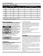
compressor for standby or overload capacity. See Table 1 for
motor sizes and air delivery capacities available.
Compressor assemblies are available with or without a factory
mounted basic or deluxe alternator/motor starter package. An
unloading feature is included on all compressors to provide
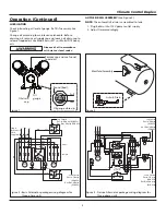
loadless starting. Models with an alternator are prewired and
ready for operation. Internal wiring allows for shutdown of
either compressor for repair while the other compressor is
running.
An alternating type operation is desirable for many reasons.
When a duplex air compressor is alternated, the temperature
of both units is kept above the ambient dew point to minimize
moisture deterioration and corrosion. Also, the reduction in
on-time provides a lower average head temperature with
reduced oil entrainment potential and improves the motor life
by holding down the average heat rise.
All units are run through a factory break-in and are tested
for air delivery, leakage and power consumption. Tank-
mounted units are shipped with a proper fill of compressor
oil in the crankcase and are furnished with an intake filter
with a replaceable cartridge. This filter is designed to remove
contaminates in the inlet air, as well as provide a quiet
operation.
All models have conveniently located oil drain and filler ports
to facilitate routine maintenance. Tanks have a condensate
drain valve with an extension for easy access. Mounting bases
are slotted to allow tension adjustments to aid in maintaining
proper compressor and motor alignment while adjusting
tension.
10
ON
8
6
TEST
20
30
5
40
OFF
0.5
0.5
45
2
4
10
sec.
min.
NOR
GREN
N
INLET
OUTLET
OUT
IN
100
0
PSI
60
20
40
PRESSURE GAGE
80
Specifications
Product
AD Series Powerex Duplex Air Compressors
Performance
Specifications
See Page 2
Lubrication
Splash Lubrication System (3/4 HP - 10 HP Models)
Operating
Voltages
1Ø
115 - 280 / 230 Volts, 60 Hz
3Ø
280 - 230 / 460 Volts, 60 Hz
Compression
Cycle
Single-Stage (3/4 HP - 10 HP Models)
Motor
Overload
Protection
1Ø
Built-in Thermal Overload (Standard)
3Ø
Magnetic Starter and Three Thermal
Overload Heaters (Optional)
Pressure
Settings
Lead
Cut-In: Factory Set at Approximately 70 psig (490 kPa)
Cut-Out: Factory Set at Approximately 90 psig (630 kPa)
Lag
Cut-In: Factory Set at Approximately 60 psig (420 kPa)
Cut-Out: Factory Set at Approximately 80 psig (560 kPa)
Overpressure
Protection
ASME Safety Valve Factory Set and Sealed at
Approximately 115 psig (805 kPa)
Outlet Air
Connections
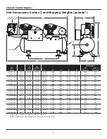
3/4 inch NPT (30, 60, and 80 Gallon Tanks)
1 inch NPT (120 and 200 Gallon Tanks)
Tank Sizes
30 Gallon to 200 Gallon
California
Ordinance
462 (L) (2)
Meets Requirements of this Ordinance
Tank Isolation Standard All Units
The performance specifications are nominal and conform to acceptable industry standards. For application at conditions beyond these
specifications, consult the local Powerex office. Powerex shall not be liable for damages resulting from misapplication or misuse of its products.


