3
Climate Control Duplex
ON
TEST
OFF
2
0.5
4
6
sec.
8
10
5
0.5
45
20
30
10
40
min.
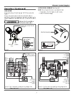
Figure 2
Manifold Assembly
Auto E-Drain
Figure 4 - Deluxe Alternator package wiring diagram for
three-phase units
AuTO E-DrAiN ASSEMBly
(See Figure 2)
NOTE:
The automatic E-drain is assembled to tank.
1. Plug E-drain into 115V power outlet supply.
2. Adjust times accordingly.
Operation (Continued)
luBriCATiON
Check lubricating oil level at gauge. Refill if necessary. See
Figure 1.
Change oil according to maintenance schedule. Before
draining oil, remove oil supply cap and loosen oil drain cap to
release trapped air. Use Mobil Rarus 427
®
or Mobil DTE heavy
oils.
Dispose of oil in accordance
with state or local codes.
Lead Switch
Cut In: 70 psig
(490 kPa)
Cut Out: 90 psig
(630 kPa)
Lag Switch
Cut In: 60 psig
(420 kPa)
Cut Out: 80 psig
(560 kPa)
L
1
L
2
L
3
IT
1
IT
2
IT
3
A1
A2
1M
Motor
1
Motor
2
2M
Selector
Switch
L
1
L
2
L
3
A1
A2
2T
1
2T
2
2T
3
X1
X2
FU
FU
FU
Alt
Figure 3 - Basic Alternator package wiring diagram for
three-phase units
L
1
Lag Switch
Cut In: 60 psig (420 kPa)
Cut Out: 80 psig (560 kPa)
L
2
L
3
Single
Disconnect
Field
Supplied
Motor
1
Motor
2
Re
d
Bl
ac
k
Bl
ue
Red
Red
Black
Blue
Alt L
Alt R
Alt
1M
2M
2M
A252
PS 2
PS 2
A251
Re
d
Re
d
2T
1
2T
2
2T
3
IT
1
IT
2
IT
3
L
1
L
2
L
3
Starter
Overload
PS 1
Alt C
A251
Lead Switch
Cut In: 70 psig
(490 kPa)
Cut Out: 90 psig
(630 kPa)
Figure 1
Remove cap and use funnel
to add oil
Oil drain
cap
Oil
gauge
Oil gauge close-up
Full
Low
Round (Red)


