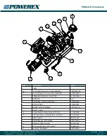
PMAC Air Compressor
Powerex
•
100 Mundy Memorial Drive
•
Mt. Juliet, TN 37122
•
USA
P 1.888.769.7979
•
F 513.367.3125
•
www.powerexinc.com
IN598601AV
•
01/2020
Page 8 of 12
TOLERANCES NOT
SPECIFIED
DRAWINGS TO CONFORM TO CURRENT REVISION OF THE FOLLOWING ANSI
STANDARDS:
Y14.3 MULTI AND SECTIONAL VIEW DWGS
Y14.5 DIMENSIONING AND TOLERANCING
SYMBOL LEGEND
0.XX
u
0.XXX
u
g
u
SOLID EDGE
DRAWING
INCH
CONFIDENTIAL DISCLOSURE
This drawing is the property of POWEREX
of the SCOTT FETZER
COMPANY and is subject to return on demand.
Its contents are confidential and must not be
copied or submitted to
outside parties for use or examination.
SHEET 1 OF 1
1:4
SCALE
ORIGINATION DATE
APPROVALS ON FILE IN PLM
ITEM ID:
MATERIAL:
DESCRIPTION
150 PRODUCTION DRIVE, HARRISON OH 45030
(888) 769-7979
DO NOT SCALE DRAWING FOR
DIMENSIONS
DRAWING NUMBER
REVISION
D
SIZE
Error: No reference
--
.05
.005
1
REVISION NOTES
DESCRIPTION
ECN
PR/NOR
ENTER DESCRIPTION
PXECXXXX
XXXXXXXX
AUTHOR
apylant
6
8
10
11
1
12
5
2
3
4
7
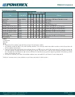
Item
Number
a2Production_Part_Num
ber
Project
Quantity
1
SDC016511AV
5HP SCROLL HP SDC
E-SERIES PUMP
1
2
SL500300AV
COUPLING, SDC, PMAC,
5HP
1
3
IP088200AV
SCROLL ADAPTER
PLATE GASKET
1
4
SL060000AV
DUPLICATE - USE
715638 INSTEAD
1
5
IP087700AV
SCROLL CHECK VALVE
(CV-157)
1
6
N/A
INVERTER, ABM, 5HP
WALL MOUNT.par
1
7
MC305000AV
MOTOR, PMAC, 5HP,
REMOTE MOUNT
1
8
IP639100AV
ISOLATOR FOOT
MOUNT PASCALEX BSB
60 135106
1
9
N/A
WELLNUT ASSEMBLY,
COMPRESSOR GREASE
PLUG, 1_4-20,
.031-.187
1
10
V-215900AV
SAFETY VALVE, 165PSI,
141 SCFM, 1/8" MNPT,
HIGH TEMP,
CONRADER
1
11
ST071515AV
COUPLING, 3/4" NPT,
BRASS
1
12
VP000501AV
3/4" INTAKE FILTER
1
9
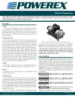
Maintenance
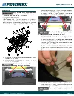
Coupling Element Replacement
The coupling element is designed to last for the life of the scroll
pump. If replacement does become necessary, remove the coupling
guard to gain access to the coupling rubber element (4). The photo
below shows the coupling guard separated from the assembly.
Before performing service, lock out and tag any
electric power source. Vent all air pressure from
the system and lock out and tag any other air sources.
Do not loosen the hexagon screws that secure the
motor adapter plate to the faceplate.
1. Loosen the screws that secure the coupling rubber element
radially to the drive hubs.
2.
DO NOT LOOSEN THE SETSCREW THAT SECURES THE DRIVE
HUB TO THE MOTOR SHAFT.
Do not use liquid thread lockers or adhesives. Do
not allow the element to become twisted while
tightening.
3.
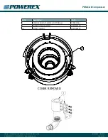
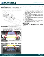
Loosen the hex head screws that hold motor adapter plate 1
to motor adapter plate 2 (see image below). The motor must
be supported during this process to prevent damaging the
assembly. Pull the motor straight back to disengage.
6. Insert the Powerex supplied screws with pre-applied Inbus Plus
thread locker into the coupling element holes and tighten the
element securing screws to 37 ft-lbs.
4.
Now the axial bolts securing the rubber coupling element to
the compressor drive hub can be removed. Do not remove
or reposition the drive hubs.
Do not move or reposition the
motor mounting plate.
Installation is the reverse of removal.
Tightening torque for the bolts that secure the rubber coupling
element to the hubs is 37 ft-lbs.
5.
To install coupling insert, lightly lubricate the body and
underside of the element securing bolts with light oil or a clean
grease.
Do not lose the 4 alignment pins installed in the
two motor adapter plates. These pins are required
to maintain alignment between the motor and the pump.

