Powerex • 100 Mundy Memorial Drive • Mount Juliet, TN 37122 • USA
P 1.888.769.7979 • F 513.367.3125 • www.powerexinc.com
IN599400AV • 21 October 2020
Page 4 of 12
Scroll Basemount Compressor
Operating & Maintenance Manual
national electric codes.
Wiring
Use solderless terminals to connect the electric power
source provided. Various electrical connections may be
provided in accordance with customer requirements.
Always ensure the connections are proper and that
when installing the final connection that proper rotation
of the compressor is witnessed.
Piping
Connect compressed air pipeline to the outlet of the
check valve.
Do not modify check valve or replace with any other
type. The scroll compressor does not require a discharge
pressure release valve for shut down unloading. When
the electric motor is de-energized, the compressed air
in the outlet pipe and after cooler will self relieve by
driving the pump in reverse a few turns. This is normal
operation.
Do not modify or restrict the air flow to or from the
after cooler without review by Powerex Engineering.
Improper cooling could lead to damage of the scroll
pump.
Operation
Before Start Up
1.
Make sure all safety warnings, labels and
instructions have been read and understood
before continuing.
2. Remove any shipping materials, brackets, etc.
3. Confirm that the electric power source and
ground have been firmly connected and are the
correct voltage for the motor.
4.
Be sure all pressure connections are tight.
5. Check to be certain all pressure relief valves, check
valves, etc. are correctly installed.
6. Check that all fuses, circuit breakers, etc. are the
proper size.
7. Make sure the inlet filter is properly installed.
8. Once power is connected to the unit, visually
check the rotation of the compressor pump. If the
rotation is incorrect, have a qualified electrician
correct the motor wiring. Motor should turn
clockwise opposite shaft end.
Start Up & Operation
The scroll basemount set is capable of operating
at 100% duty at full load. For most applications, the
set will be controlled in response to pressure. Start-
stop control is to be used. The low pump inertia
minimizes the start up amp surge associated with other
compressor types. Tank size and pressure settings
must be selected to keep the starts per hour below 16
and to allow at least 12 seconds of off time between
starts.
Factory installed sheaves are sized to achieve the
appropriate speed for the installed pump. Changing
sheave size is not recommended.
Adjusting Belt Tension
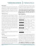
Moving Parts! Lock out power
before servicing unit!
After the first 200 to 500 running hours, or at any time
chirping is heard on startup, check the belt tension. If
tension is below 25 pounds on either belt, increase the
center distance using the motor slide base so that belt
tension is 45 to 50 pounds. Follow the Belt Replacement
Procedure below, skipping steps 3 and 4 to make this
adjustment.
Belt Replacement Procedure
1.
Remove the belt guard.
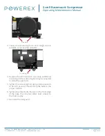
2. Loosen the two slide bolts near the motor pulley
and the two slide bolts on the front edge of the
base. Loosen the bolts just enough to allow the
slide base to move. Do not fully remove the slide
bolts.
Slide bolts


