background image

2

Scroll Air Compressors Tankmount/Basemount

Installation

RECEIVING THE UNIT

Immediately upon receipt of the scroll
compressor, the unit should be inspect-
ed for any damage which may have
occurred in shipment. Any shipping
damage must be immediately filed with
the freight carrier.

The compressor nameplate should be
checked to see if the unit is the correct
model and voltage as ordered.

APPLICATION

When the scroll compressor is to be
used in applications other than the
compressing of atmospheric air, please
contact a Powerex representative for
engineering and warranty information
at 1-888-769-7979.

INSTALLATION SITE

1. The scroll compressor must be locat-

ed in a clean, well lit and well venti-
lated area.

2. The area should be free of excessive

dust, toxic or flammable gases, mois-
ture, water and direct sunlight.

3. Never install the compressor where

the ambient temperature is higher
than 104

o

F or where humidity is high.

4. Clearance must allow for safe, effec-

tive inspection and maintenance.

5. If necessary, use metal shims or leveling

pads to level the compressor. Never use
wood to shim the compressor.

VENTILATION

1. If the scroll compressor is located in a

totally enclosed room, an exhaust fan
with access to outside air must be
installed.

2. Never restrict the cooling fan

exhaust air.

3. Never locate the compressor where

hot exhaust air from other heat gen-
erating units may be pulled into the
unit.

WIRING

Refer to the general product manual.
All electrical hook-ups must be per-
formed by a qualified electrician.
Installations must be in accordance
with local and national electrical codes.

Use solderless terminals to connect the
electric power source.

PIPING

Refer to the general product manual.

1. Make sure the piping is lined up

without being strained or twisted
when assembling the piping for the
scroll compressor.

2. Appropriate expansion loops or

bends should be installed at the com-
pressor to avoid stresses caused by
changes in hot and cold conditions.

3. Piping supports should be anchored

separately from the compressor to
reduce noise and vibration.

4. Never use any piping smaller than

the compressor connection.

5. Use flexible hose to connect the out-

let of the compressor to the piping so
that the vibration of the compressor
does not transfer to the piping.

SAFETY VALVES

Tank mounted compressors are shipped
from the factory with safety valves
installed in the tank. The flow capacity
of the safety valve is equal to or greater
than the capacity of the compressor.

1. The pressure setting of the safety

valve must be no higher than the
maximum working pressure of the
tank.

2. Safety valves should be placed ahead

of any possible blockage point in the
system, i.e. shutoff valve.

3. Avoid connecting the safety valve

with any tubing or piping.

4. Manually operate the safety valve

every six months to avoid sticking or
freezing.

Operation

BEFORE START UP

1. Make sure all safety warnings, labels

and instructions have been read and
understood before continuing.

2. Remove any shipping materials,

brackets, etc.

3. Confirm that the electric power

source and ground have been firmly
connected.

4. Be sure all pressure connections are

tight.

5. Check to be certain all safety relief

valves, etc., are correctly installed.

6. Check that all fuses, circuit breakers,

etc., are the proper size.

7. Make sure the inlet filter is properly

installed.

8. Confirm that the drain valve is closed.

9. Visually check the rotation of the

compressor pump.  If the rotation is
incorrect, have a qualified electrician
correct the motor wiring.

START-UP AND OPERATION

1. Follow all the procedures under

“Before start-up” before attempting
operation of the compressor.

2. Switch the electric source breaker on. 

3. Open the tank discharge valve com-

pletely.

4. Check that the compressor operates

without excessive vibration, unusual
noises or leaks.

5. Close the discharge valve completely.

6. If the pressure does not rise on a

three phase unit, turn the unit off.
Have a qualified electrician switch
the breaker OFF and exchange the L1
and L2 connections (two out of three
phases of electric source) inside the
magnetic starter enclosure.

7. Check the discharge pressure. Also

make sure the air pressure rises to the
designated pressure setting by check-
ing the discharge pressure gauge.

8. Check the operation of the pressure

switch by opening the tank outlet
valve and confirming the compressor
starts as pressure drops.

Minimum Clearances

Above

24”

Drive belt side

12”

Other sides

20”

Summary of Contents for SBS0307

Page 1: ...let at the cen ter of the fixed scroll so no valves are needed Scroll Tankmount Basemount Air Compressors TIP SEAL The tip seal on the scroll compressor is self lubricated and allows the unit to operate efficiently without oil and expensive filtration The tip seal should be replaced every 10 000 hours of operation BEARINGS The bearings on the scroll compressor are regreaseable to allow extended co...

Page 2: ...r connection 5 Use flexible hose to connect the out let of the compressor to the piping so that the vibration of the compressor does not transfer to the piping SAFETY VALVES Tank mounted compressors are shipped from the factory with safety valves installed in the tank The flow capacity of the safety valve is equal to or greater than the capacity of the compressor 1 The pressure setting of the safe...

Page 3: ...kmount Duplex Aftercooler Scroll Air End Pressure Switch Starter ASME Receiver 30 60 Gallon Auto Drain optional ASME Receiver 30 60 Gallon Beltguard Pulley Belt 3 4 NPT Outlet Aftercooler Scroll Air End Aftercooler Scroll Air End ASME Receiver Tank Lag Pressure Switch Starter Lead Pressure Switch Motor 3 or 5 HP Beltguard Pulley Belt 3 4 NPT Outlet ...

Page 4: ...280 390 STS130 3 1 8 6 230 17 30 60 39x22x35 51x23x39 295 405 STS050 5 3 14 7 208 230 460 13 7 13 2 6 6 30 60 39x22x35 51x23x39 300 410 STS151 5 1 14 7 230 25 30 60 39x22x35 51x23x39 310 420 Scroll Tankmount Simplex Model STS SCFM Full Load Gallon Dimension Ship Model HP Phase 100 PSIG Voltage Amperage Tank LxWxH Weight Lbs STD030 3 2 3 17 2 208 230 460 17 4 16 0 8 0 80 64x26x40 650 STD130 3 2 1 1...

Page 5: ...nfirm operation Every 2 500 hrs or less Pressure gauge Inspect Every 2 500 hrs or less Inspect Replace NOTES 1 Inspect and perform maintenance periodically according to maintenance schedule 2 The maintenance schedule relates to the normal operating conditions If the circumstances and load condition are adverse shorten the cycle time and do maintenance accordingly 3 The tension of the V belt should...

Page 6: ...lex Single Phase 208 230 Volts Field furnished power supply Disconnect Red Black Motor Red Red Pressure electric switch L1 L2 T1 T2 Open Red Black Red Red Red Red Black Red Blank Main disconnect and branch circuit protection to be installed by a qualified electrician in accordance with national and local codes ...

Page 7: ...ount Simplex Three Phase 208 230 460 Volts Disconnect Black Motor Red Pressure electric switch L1 L2 T1 T2 L3 T3 Blue Red Red Red Black Blue Field furnished power supply Main disconnect and branch circuit protection to be installed by a qualified electrician in accordance with national and local codes ...

Page 8: ...TA 3 PHASE 60 Hz OVERLOAD SETTINGS TOTAL PANEL F L A F L A TOTAL UNIT 208 230 460 PANEL 208 230 460 HP VOLT VOLT VOLT HP VOLT VOLT VOLT 3 10 29 9 2 4 6 6 21 1 18 9 9 7 5 15 56 14 0 7 0 10 31 6 28 5 14 5 Figure 6 3 5 HP Duplex Three Phase 208 230 460 Volts ...

Page 9: ...700AV 1 5 HP BT010700AV 2 9 Δ Motor pulley 3 HP PU009753AV 1 5 HP PU009754AV 1 10 Pressure switch CW207559AV 1 11 Starter 3 HP 230V 1 Phase JP001045AV 1 5 HP 230V 1 Phase IP001046AV 1 3 HP 230V 3 Phase JP001047AV 1 5 HP 230V 3 Phase JP001049AV 1 3 HP 460V 3 Phase JP001048AV 1 5 HP 460V 3 Phase JP001050AV 1 12 90 Elbow ST074204AV 1 13 1 2 Flare ST126207AV 1 14 Discharge tube SL300900AV 1 15 90 Flar...

Page 10: ... HP 460V 3 Phase JP001048AV 1 5 HP 460V 3 Phase JP001050AV 1 3 Receiver tank 30 gallon AR024700AJ 1 60 gallon AR022500AJ 1 4 Beltguard BT303900AV 1 5 Motor pulley 3 HP PU009753AV 1 5 HP PU009754AV 1 6 Guard plate BG217500AV 1 7 Aftercooler SL300100AV 1 8 Tube air end aftercooler SL301000AP 1 9 Tube aftercooler tank SL300900AP 1 10 Check valve IP087700AV 1 11 Pressure gauge GA016701AV 1 12 Safety v...

Page 11: ...se ZZ000420AJ 1 5 HP 460V 3 Phase ZZ000421AJ 1 3 Receiver tank 80 gallon AR022900AJ 1 120 gallon AR023600AJ 1 4 Beltguard BT303900AV 1 5 Belt 3 HP BT010700AV 2 5 HP BT010700AV 4 6 Motor pulley 3 HP PU009753AV 1 5 HP PU009754AV 1 7 Guard plate BG217500AV 1 8 Aftercooler SL300100AV 1 9 Tube air end aftercooler SL301000AP 1 10 Tube aftercooler tank SL300900AP 1 11 Check valve IP087700AV 1 12 Pressure...

Page 12: ... THE DATE OF PURCHASE AND TO THE EXTENT PERMITTED BY LAW ANY AND ALL IMPLIED WARRANTIES ARE EXCLUDED THIS IS THE EXCLUSIVE REMEDY AND LIABILITY FOR CONSEQUENTIAL DAMAGES UNDER ANY AND ALL WAR RANTIES IS EXCLUDED TO THE EXTENT EXCLUSION IS PERMITTED BY LAW All claims pertaining to the merchandise in this schedule with the exception of warranty claims must be filed with POWEREX within 6 months of th...

Page 13: ...could result in personal injury and or prop erty damage Retain instructions for future reference Powerex 150 Production Drive Harrison OH 45030 USA Scroll Air Compressor Service and Maintenance Breathable Air Warning This compressor pump is not equipped and should not be used as is to supply breathing quality air For any application of air for human consumption the air compressor pump will need to...

Page 14: ...se delivery chart See Grease Delivery chart below Figure 2 Use only Powerex genuine grease Pump grease gun before feeding this eliminates air from the grease passage of the extension adapter Complete Grease Kit Part Number IP616200AJ and Grease Tube Part Number IP600000AV 4 Replace plastic dust cap The bearings on the scroll compressor are regreaseable to allow extended compressor life Service sho...

Page 15: ... Note 3 Pressure Switch Confirm operation Magnetic starter Inspect Replace if contact points deteriorated Safety valve Confirm operation Every 2 500 hrs or less Pressure gauge Inspect Every 2 500 hrs or less Inspect Replace NOTES 1 Inspect and perform maintenance periodically according to maintenance schedule 2 The maintenance schedule relates to the normal operating conditions If the circumstance...

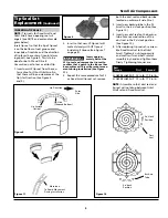
Page 16: ...nside Per OSHA regulations ALL power must be locked out before per forming any maintenance The Tip Seal Set is a replacement part for SLAE03 and SLAE05 air ends Please read these instructions thor oughly and carefully to ensure correct replacement NOTE Replace tip seal on SLAE03HP and SLAE50HP at 5 000 hours when operated at 145 psig See Scroll Service and Maintenance Video for Audio and Visual In...

Page 17: ...seal inside Scroll Groove See Figure 7 on page 4 Insert approxi mately half of the LP tip seal and remove the tip seal to confirm that a notch in the tip seal has been achieved This will prevent move ment during installation See Figure 11 3 Repeat the same procedure for FS or Fixed Scroll tip seal set remove CAUTION INSERTING TIP SEALS Tip Seal Set Replacement Continued both the dust seal and back...

Page 18: ...6 Scroll Air Compressors Figure 12 Compressor Parts 19 1 2 4 3 6 5 8 7 10 9 12 11 14 15 16 17 18 15 17 A A B B 13 ...

Page 19: ...ate IP602100AV IP602100AV IP602100AV IP602100AV 1 10 Cartridge Filter IP032901AV IP032901AV IP032901AV IP032901AV 1 11 Intake Pipe IP602200AV IP602200AV IP602200AV IP602200AV 1 12 Intake Filter Cover IP016101AV IP016101AV IP016101AV IP016101AV 1 13 Filter Cover Pipe IP602300AV IP602300AV IP602300AV IP602300AV 6 14 Fan Duct Gasket 2 IP602400AV IP602400AV IP602400AV IP602400AV 1 15 O Ring IP603200AV...

Page 20: ...strate and describe the products in this literature accurately however such illustrations and descriptions are for the sole purpose of identification and do not express or imply a warranty that the products are merchantable or fit for a particular purpose or that the products will necessarily conform to the illustrations or descriptions Product Suitability Many jurisdictions have codes and regulat...

Reviews: