16
Scroll Enclosure Air Compressors
Scheduled Maintenance
Per OSHA regulations, lockout
compressor system from all
power sources BEFORE performing any maintenance.
INTAKE FILTER
1. Remove the front panel of the unit.
2. Remove the air inlet housing, the wing nut and the inlet
fi lter element.
3. Clean the inlet fi lter element with compressed air or
replace with a new element.
NOTE:
Never clean fi lter element with solvents or water.
VENTILATION SCREEN
1. Remove
the ventilation screen located at the rear of the unit.
2. Clean with compressed air or soap and water, if necessary.
INSPECT V-BELT TENSION
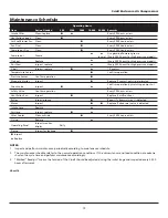
1. Check V-Belt tension with tension gauge.
2. Adjust to the specifi cations listed in Chart 15.
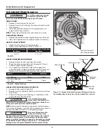
GREASE COMPRESSOR BEARINGS
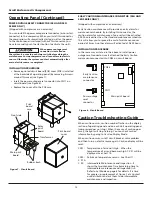
1. Remove the plastic dust cap from the airend.
2. Move the compressor pulley until the grease fi tting is
visible through the dust cap hole.
3. Use a grease gun extension adapter to engage the
grease fi tting and supply the proper volume of grease as
indicated on the grease delivery chart. See Chart 16.
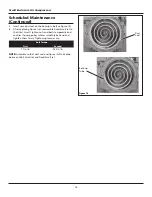
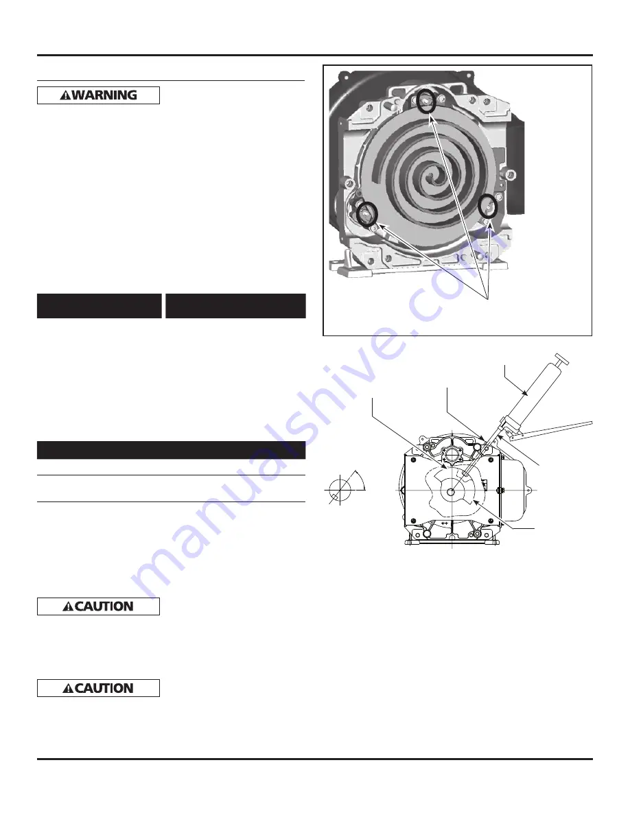
GREASE PIN CRANK BEARING (FIGURE 10)
1. Remove the fan duct (2) (Key #6).
2. Remove the nuts and bolts and then the fi xed scroll from
the air end.
3. Grease all three pin crank bearings as indicated on the
grease delivery Chart 14 above.
Use only Powerex genuine
grease (Part # IP600000AV), or
equivalent. Pump grease gun before feeding to eliminate air
from grease passage of the needle adapter.
NOTE:
Each pump of the grease gun equals 0.65g of grease.
The volume of grease is less after the 2nd pump since some of
the grease supply will remain in the grease passage.
The grease fi tting, located in
the center of the pin crank
bearing, feeds only the orbit scroll side bearing. Use a needle
adapter to supply grease to the housing side bearing. Pump
grease gun before feeding to eliminate air from grease passage
of the needle adapter. Hold grease gun for 5 - 10 seconds after
feeding to prevent grease blowback from the grease fi tting.
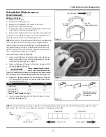
New Belt Load ± Defl ection
Kg/ 10mm
Existing Belt Load ± Defl ection
Kg/ 10mm
6 ± 0.5
5.5 ± 0.5
Chart 15
Model
1st Time
2nd Time
O.S. Bearing
7 times
6 times
Pin Crank Bearing
O.S. Side
7 times
7 times
Chart 16 - Grease Delivery
Figure 10 - Airend: to locate the grease fi tting on the coun-
ter weight, place the key way on the crankshaft as shown.
Key Way
Counter
Weight
Extension
Adapter
Grease Gun
Plastic Dust Cap
Grease Fitting
52°
Grease fi ttings for
pin crank bearings
Figure 9

