background image

4

Scroll Enclosure Air Compressors

General Safety Information 
(Continued)

15.  Always provide a clean air source for your compressor. 

Keep all piping direct and short when using an outside 
air source.

16.  Locate compressor inlet system away from possible 

ingestion of fl ammable or toxic vapors, water, dirty air or 
air temperatures exceeding 104°F.

17.  Never set the pressure to a higher setting than the one 

provided from the factory.

18.  Check all gauges daily to be sure the compressor is 

operating correctly.

19  Follow all directions for maintenance. Check all safety 

devices according to instructions.

20.  Never attempt to lift or move the compressor except 

when using the proper lifting procedures.

21.  Make sure all electrical components follow the National 

Electric code and all state and local codes when installing 
the compressor.

22  Do not operate the compressor if unusual noise or 

vibration occurs.

23.  Keep all panels in place at all times.

24.  Standard motors are not appropriate for dirty, wet or 

explosive areas.

25.  All service should be performed by trained and qualifi ed 

people only.

26.  The Drive Belt tension should be checked often during 

initial operation of the compressor.

27.  Never substitute oil bath or oil wetted fi lters for the inlet 

fi lters provided with the compressor.

Installation

INSTALLATION SITE

1.  The scroll compressor must be located in a clean, well lit 

and well ventilated area. A contaminated area can clog 
the intake fi lter and / or intake metal mesh.

2.  The area should be free of excessive dust, toxic or 

fl ammable gases, moisture and direct sunlight.

3.  Never install the compressor where the ambient 

temperature is higher than 104°F or lower than 32°F 
or where humidity is high. High humidity will cause 
electrical short circuit and rusting of components.

4.  Clearance must allow for safe, effective inspection and 

maintenance. 24 inch of clearance for sides, 40 inch 
clearance from the top is recommended.

5.  If necessary, use metal shims or leveling pads to level the 

compressor. Never use wood to shim the compressor.

VENTILATION

1.  If the scroll compressor is located in a totally enclosed 

room, an exhaust fan with access to outside air must be 
installed.

2.  Never restrict the cooling fan exhaust air.

3.  Vent the exhaust air outside to prevent the compressor 

from operating at high temperatures and shutting down.

4.  Never locate the compressor where hot exhaust air from 

other heat generating units may be pulled into the unit.

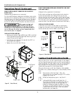
SUGGESTED VENTILATION SYSTEM

1)  The following ventilation capacity is designed to keep 

the temperature rise inside the room to be max. 10°F. 
Since the calculation is based on zero static pressure, 
the actual ventilation capacity should be larger than the 
capacity value listed in Chart 1.

FRESH

AIR IN

EXHAUST

AIR OUT

FRESH

AIR IN

EXHAUST

AIR OUT

8 inches to

12 inches

Clearance

Setup A

Setup B

Figure 3

Model - Setup B

10 HP

15 HP

20 HP

30 HP

40 HP

Ventilation 
Capacity (cfm)

885

1415

1770

2830

3535

Model - Setup A

10 HP

15 HP

20 HP

30 HP

40 HP

Ventilation 
Capacity (cfm)

2650

3885

5300

7770

10595

Chart 1

Summary of Contents for SED1007

Page 1: ...rex Oilless Rotary Scroll Air Compressor has advanced scroll compressor technology through the development of a completely oilless unit The Powerex Scroll Compressor offers a dynamically balanced air end which insures vibration free operation The rotary design permits a continuous 100 duty cycle No oil separation oil filtration or inlet valves are required on the Powerex Scroll unit The compressor...

Page 2: ...rstand This information is provided for SAFETY and to PREVENT EQUIPMENT PROBLEMS To help recognize this information observe the following symbols Danger indicates an imminently hazardous situation which if not avoided will result in death or serious injury Warning indicates a potentially hazardous situation which if not avoided could result in death or serious injury Caution indicates a potentiall...

Page 3: ... HOT parts of the compressor such as the air end discharge pipe aftercooler motor etc 7 Keep flammable gases away from the compressor Parts of the compressor become very hot during operation and the vapors from flammable gases may cause the unit to explode 8 Never use flammable or toxic solvents to clean the compressor or any of the unit s parts 9 Do not remove or tamper with any safety devices gu...

Page 4: ...can clog the intake filter and or intake metal mesh 2 The area should be free of excessive dust toxic or flammable gases moisture and direct sunlight 3 Never install the compressor where the ambient temperature is higher than 104 F or lower than 32 F or where humidity is high High humidity will cause electrical short circuit and rusting of components 4 Clearance must allow for safe effective inspe...

Page 5: ...hart 2 as a guideline for sizing the air receiver 1 Make sure the piping is lined up without being strained or twisted when assembling the piping for the scroll compressor 2 Appropriate expansion loops or bends should be installed at the compressor to avoid stresses caused by changes in hot and cold conditions 3 Piping supports should be anchored separately from the compressor to reduce noise and ...

Page 6: ...e on a three phase unit turn the unit off the unit is running backwards Have a qualified electrician switch the breaker OFF and exchange two out of three phases of electric source 8 Check the discharge pressure Also make sure the air pressure rises to the designated pressure setting by checking the discharge pressure gauge CONTROL LOGIC SEQUENCING ORDER Since the compressors are designed using mul...

Page 7: ...me and restarts the air end whose operating time has been shorter thus resulting in equalization of operating time of each air end and operation with a min quantity of air ends in accordance with air consumption and energy saving operation by eliminating waste of electricity 2 Prevention of long term operation When operating time of an air end exceeds the initial setting time it changes operation ...

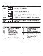
Page 8: ...e each pump starts 3 Service Mode In order to select Service Mode push Mode Selector Switch so that Service Mode light is illuminated By Item Selector Switch you can determine causes and conditions when problems occur as indicated in Charts 5 and 7 It functions only when compressor stops 4 Set Mode Push Mode button so that Set Mode light is illuminated Item button can show each of the set contents...

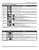
Page 9: ... If the unit has no air end to display the indicator will always display underline Operating condition of Unit No 1 SEO and SEH series Displays operating condition of present Unit No 1 left side which consists of air ends no 1 4 Display contents are the same as illustrated above Operating condition of Unit No 2 SEO and SEH series Displays operating condition of present Unit No 2 right side which c...

Page 10: ... in C when emergency stops occur This display means 58 C When air end temperature is less than 15 C or other failure like cut of temperature sensor occurs displays Operating Time Shows Operating Time in x 10 hours when emergency stops occur This display means 230 hours Operating Mode Shows Operating Mode in number when emergency stops occur Refer to Chart 9 for Operating Mode Chart 5 Caution and S...

Page 11: ... and inspection in terms of 10 hours The first figure is 980 480 for high pressure models and decreases as operating time becomes longer Group Control Shows set situation of Group Control means that Group Control mode OFF is set means that Group Control mode ON is set If Group control mode ON is set ON OFF button does not work When either displays it can be changed by pushing reset switch Chart 8 ...

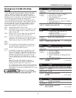
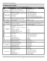
Page 12: ...the standard maintenance schedule This will allow you to spread the cost of maintenance over period of times Another alarm will activated at 9 800 hours INSTALLATION PROCEDURE In the same way as stated in the above to install power outage reset connector insert attached the Early Caution maintenance connector into CN26 on circuit board Caution Troubleshooting Guide When caution occurs caution numb...

Page 13: ...ature compressor air end stops See Chart 12 EX32 Rise of current If current becomes very high EX32 displays and compressor stops See Chart 13 EX41 Emergency stop by high pressure When pressure is higher than cut out pressure by 15 psig E41 displays and compressor stops Only SEH and SEO series EX60 EX61 EX63 Communications failure between the main panel circuit board and circuit board on each Unit ...

Page 14: ...nd reengage the circuit breaker Replace circuit board It starts but then stops E21 or E22 are displayed High ambient temperature or bad ventilation Clogging of aftercooler fins or intake wire screen Failure of ventilating fan Damage to intake hose Cooling passage of air end clogs High exhaust pressure Improve installation environment and ventilation Clean Replace Replace Inspect Inspect E32 is dis...

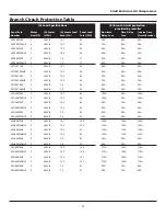
Page 15: ... SEH300720BHP SEH300730B SEH300730BHP SEH300740B SEH300740BHP 5 5 5 5 5 5 208V 3 208V 3 230V 3 230V 3 460V 3 460V 3 16 7 16 7 15 2 15 2 7 6 7 6 100 100 91 91 47 47 SEO400720B SEO400720BHP SEO400730B SEO400730BHP SEO400740B SEO400740BHP 5 5 5 5 5 5 208V 3 208V 3 230V 3 230V 3 460V 3 460V 3 16 7 16 7 15 2 15 2 7 6 7 6 134 134 121 121 61 61 Branch Circuit Protection Table B Branch circuit protection ...

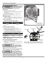
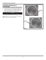
Page 16: ... and bolts and then the fixed scroll from the air end 3 Grease all three pin crank bearings as indicated on the grease delivery Chart 14 above Use only Powerex genuine grease Part IP600000AV or equivalent Pump grease gun before feeding to eliminate air from grease passage of the needle adapter NOTE Each pump of the grease gun equals 0 65g of grease The volume of grease is less after the 2nd pump s...

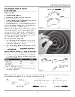
Page 17: ...r OS or Orbit Scroll so that there will be no clearance at the tip start section See Figure 11 and 12 2 Insert so that new LP tip seal will contact closely with HP tip seal inside Scroll Groove Insert approxi mately half of the LP tip seal and remove the tip seal to confirm that a notch in the tip seal has been created This will prevent movement during installation See Figure 8 3 Repeat the same p...

Page 18: ...ssemble Fixed Scroll set to the Orbit Scroll Tighten nuts and bolts temporarily and confirm if pump pulley rotates smoothly by hand and tighten them firmly Tightening torques are NOTE Assemble so that dust seal and tip seal will not drop between Orbit Scroll set and Fixed Scroll set Dust Seal Back up Tube Figure 14 Bolt Torque First Second 17 in lb 265 in lb ...

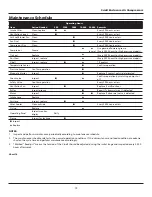
Page 19: ...eriorated Check valve Inspect Confirm operation by watching pump shut off Safety Valve Confirm operation Every 500 hours or less Ventilation Fan Inspect Replace if malfunctions Pulley Inspect groove Repair if abnormal wear is detected Motor Inspect Replace if abnormal noise is detected Intake hose Replace Air Hose Inspect replace After Cooler Clean outside Every 5000 hours or less O ring Replace O...

Page 20: ...e top panel from the scroll cabinet to access the operating panel Remove the plastic cover from the backside of the operating panel Lift the expansion PCB from the operating panel 3 Output wires should be connected between terminals 3 and 4 The dry contacts are normally open when there is a fault the contacts close The contact rating is as follows 200 V AC 1A maximum 4 For larger load devices such...

Page 21: ... Enclosure Air Compressors 2 TI 2 TI 4 T2 4 T2 6 T3 6 T3 1 2 3 4 1 4 1 4 2 4 2 4 3 4 3 4 4 4 4 6 7 1 7 1 7 2 7 2 13 13 14 14 15 15 16 16 11 11 9 12 12 10 10 8 5 17 17 Figure 16 Parts Diagram SET1507E SET1507EHP ...

Page 22: ...22 Scroll Enclosure Air Compressors 6 T3 4 T2 2 TI 1 2 3 4 1 4 2 4 3 4 4 6 7 1 7 2 13 14 15 16 11 9 12 10 8 5 17 7 3 Figure 17 Parts Diagram SEQ2007E SEQ2007EHP ...

Page 23: ...2899060 92899060 92899060 92803070 92803070 1 7 2 Intake hose 2 92805070 92805070 92805070 92805070 92899060 92899060 1 2 2 7 3 Intake hose 3 N A N A N A N A 92805070 92805070 1 8 Temperature transducer 02801001 02801001 02801001 02801001 02801001 02801001 2 3 4 9 Pressure sensor 97992133 97992133 97992133 97992133 97992133 97992133 1 10 Check valve CV 157 CV 157 CV 157 CV 157 CV 157 CV 157 2 3 4 ...

Page 24: ...24 Scroll Enclosure Air Compressors 4 3 1 6 11 2 9 12 7 5 10 8 Figure 18 Service Parts Diagram ...

Page 25: ...uct 2 02519042 02519042 1 6 Fan Cover IP601700AV IP601700AV 1 7 Fan Dust Gasket 1 IP601900AV IP601900AV 1 8 Heat Insulation Pipe IP602000AV IP602000AV 1 9 Fan Duct Gasket 2 IP602400AV IP602400AV 1 10 Long Nipple 96647011 96647011 1 11 Dust Cap IP603500AV IP603500AV 1 12 Tip Seal Set 92832070 92832080 1 Grease Gun Kit IP616201AJ IP616201AJ Grease Gun IP616101AJ IP616101AJ Grease IP600000AV IP600000...

Page 26: ...26 Scroll Enclosure Air Compressors Maintenance Service Record Date Maintenance Performed Replacement Components Required ...

Page 27: ...27 Scroll Enclosure Air Compressors Notes ...

Page 28: ... s written instructions iii that have been materially modified without the prior written approval of Powerex or iv that experience failures resulting from operation either intentional or otherwise in excess of rated capacities or in an otherwise improper manner f The warranty provided herein shall not apply to i any defects arising from corrosion abrasion use of insoluble lubricants or negligent a...

Reviews: