background image


Scroll Air Compressor Service and Maintenance

 Please read and save these instructions. Read carefully before attempting to assemble, install, operate or maintain the product 
described. Protect yourself and others by observing all safety information. Failure to comply with instructions could result in 
personal injury and/or property damage! Retain instructions for future reference.

 Powerex • 150 Production Drive • Harrison, OH  45030 • USA
1-888-769-7979 • www.powerexinc.com

IN557305AV 1/14

Description

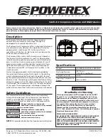
The Powerex Oilless Rotary Scroll Air Compressor has 
advanced scroll compressor technology through the 
development of a completely oilless unit. 

The Powerex Scroll Compressor offers a dynamically balanced 
air end which insures vibration-free operation. The rotary 
design permits a continuous 100% duty cycle. No oil 
separation, oil fi ltration, or inlet valves are required on the 
Powerex Scroll air compressor.

The Powerex oilless rotary scroll air compressor is based on 
the theory of scroll compression. A scroll is a free standing, 
intricate spiral bounded on one side by a solid, fl at plane or 
base. A scroll set, the basic compression element of a scroll 
compressor, is made up of two identical spirals which form 
right and left hand parts. One of these scroll components 
is indexed or phased 180° with respect to the other so the 
scrolls can mesh. 

Crescent-shaped gas pockets are formed and bounded by 
the spirals and the base plate of both scrolls. As the orbiting 
scroll is orbited around the fi xed scroll, the pockets formed 
by the meshed scrolls follow the spiral toward the center and 
diminish in size. The orbiting scroll is prevented from rotating 
during this process so the 180° phase relationship of the scrolls 
is maintained. The compressor’s inlet is at the outer boundary 
of the scrolls. The compressed gas is discharged through the 
outlet at the center of the fi xed scroll so no valves are needed.

 Safety Guidelines

This manual contains information that is very important 
to know and understand. This information is provided for 
SAFETY and to PREVENT EQUIPMENT PROBLEMS. To help 
recognize this information, observe the following symbols.


Danger indicates an imminently 

  hazardous situation which, if not avoided, 

WILL result in death or serious injury.


Warning indicates a potentially  

  hazardous situation which, if not avoided, 

COULD result in death or serious injury.


Caution indicates a potentially  

  minor or moderate injury.

NOTE:

 This provides information that requires special attention.

Specifi cations

Product

SLAE03EB, SLAE05E, SLAE05EHP

Discharge Pressure

95-115 psi 
(125-145 psi optional)

Compression Cycle

Scroll

Operating Temperature 
Range

32°F to 104°F

Breathable Air Warning

This compressor/pump is NOT equipped and should NOT 
be used “as is” to supply breathing quality air. For any 
application of air for human consumption, you must fi t 
the air compressor/pump with suitable in-line safety and 
alarm equipment. This additional equipment is necessary 
to properly fi lter and purify the air to meet minimal 
specifi cations for Grade D breathing as described in 
Compressed Gas Association Commodity Specifi cation 
G 7.1 - 1966, OSHA 29 CFR 1910. 134, ANSI and/or Canadian 
Standards Associations (CSA).

DISCLAIMER OF WARRANTIES

IN THE EVENT THE COMPRESSOR IS USED FOR THE PURPOSE 
OF BREATHING AIR APPLICATION AND PROPER IN-LINE 
SAFETY AND ALARM EQUIPMENT IS NOT SIMULTANEOUSLY 
USED, EXISTING WARRANTIES ARE VOIDED, AND POWEREX 
DISCLAIMS ANY LIABILITY WHATSOEVER FOR ANY LOSS, 
PERSONAL INJURY OR DAMAGE.

Summary of Contents for SLAE03EB

Page 1: ...ng during this process so the 180 phase relationship of the scrolls is maintained The compressor s inlet is at the outer boundary of the scrolls The compressed gas is discharged through the outlet at the center of the fixed scroll so no valves are needed Safety Guidelines This manual contains information that is very important to know and understand This information is provided for SAFETY and to P...

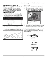
Page 2: ...volume of grease as indicated on the grease delivery chart See Grease Delivery chart on Page 2 and on Figure 1 Use only Powerex genuine grease Pump grease gun before feeding This eliminates air from the grease passage of the extension adapter 4 Replace plastic dust cap Greasing Pin Crank Bearings The bearings on the scroll compressor are regreaseable to allow extended compressor life Service shoul...

Page 3: ...firmation of the Parts 1 Confirm if the tip seal set you purchased is correct for the air end you are repairing See part number 12 on Page 7 for tip seal set and corresponding pump model number One tip seal set contains all of the items in Figure 3 below 2 Confirm if the following parts are included See Figure 3 1 2 5 6 4 3 Figure 3 Tip Seal Removal Figure 4 Item No Description Qty 1 HP tip seal f...

Page 4: ...otch in the tip seal has been created This will prevent movement during installation See Figure 7 3 Repeat the same procedure for FS or Fixed Scroll tip seal set remove both the dust seal and backup tube located on outermost side FS set 4 Insert new backup tube in the FS Scroll in the 6 o clock position See Figure 8 5 Insert new dust seal on the backup tube 6 After replacing tip seal set reassembl...

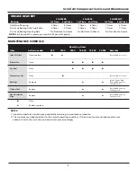
Page 5: ...according to maintenance schedule 2 The maintenance schedule relates to the normal operating conditions If the circumstances and load condition are adverse shorten the cycle time and do maintenance accordingly MAINTENANCE SCHEDULE GREASE DELIVERY SLAE03EB SLAE05E SLAE05EHP Bearing 1st Time 2nd Time 1st Time 2nd Time 1st Time 2nd Time Orbit Scroll Bearing 5 Times 4 Times 7 Times 6 Times 7 Times 6 T...

Page 6: ...6 Scroll Air Compressor Service and Maintenance Maintenance Log Date Maintenance Required Maintenance Performed ...

Page 7: ...7 Scroll Air Compressor Service and Maintenance Maintenance Log Date Maintenance Required Maintenance Performed ...

Page 8: ...8 Scroll Air Compressor Service and Maintenance Figure 9 Compressor Parts 6 1 3 4 2 12 5 7 11 8 10 FS cover 14 15 13 13a 9 ...

Page 9: ...AV IP602000AV 1 9 Fan Duct Gasket 2 IP602400AV IP602400AV IP602400AV 1 10 Long Nipple 96647011 96647011 96647011 1 11 Dust Cap IP603500AV IP603500AV IP603500AV 1 12 Tip Seal Set 92834090 92832070 92832080 1 13 Filter Assembly ST073925AV ST073925AV ST073925AV 1 13a Filter Element ST073921AV ST073921AV ST073921AV 1 14 Adaptor Plate IP088400AV IP088400AV IP088400AV 1 15 Intake Gasket IP088200AV IP088...

Page 10: ...10 Scroll Air Compressor Service and Maintenance Notes ...

Page 11: ...hs from the date of shipment by Powerex or thirty six 36 months from the documented date of startup or ten thousand 10 000 hours of use whichever occurs first Supplier s repair or replacement of any Product shall not extend the period of any warranty of any Product This warranty applies to the exchange of part s found to be defective by an Authorized Powerex Service Representative only d Replaceme...

Page 12: ...stallation and or use of Products for certain purposes which may vary from those in neighboring areas While Powerex attempts to assure that its Products comply with such codes it cannot guarantee compliance and cannot be responsible for how the product is installed or used Before purchase and use of a Product please review the Product applications and national and local codes and regulations and b...

Reviews: