background image


5

2. SAFETY GUIDELINES 


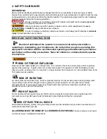
DEFINITIONS  

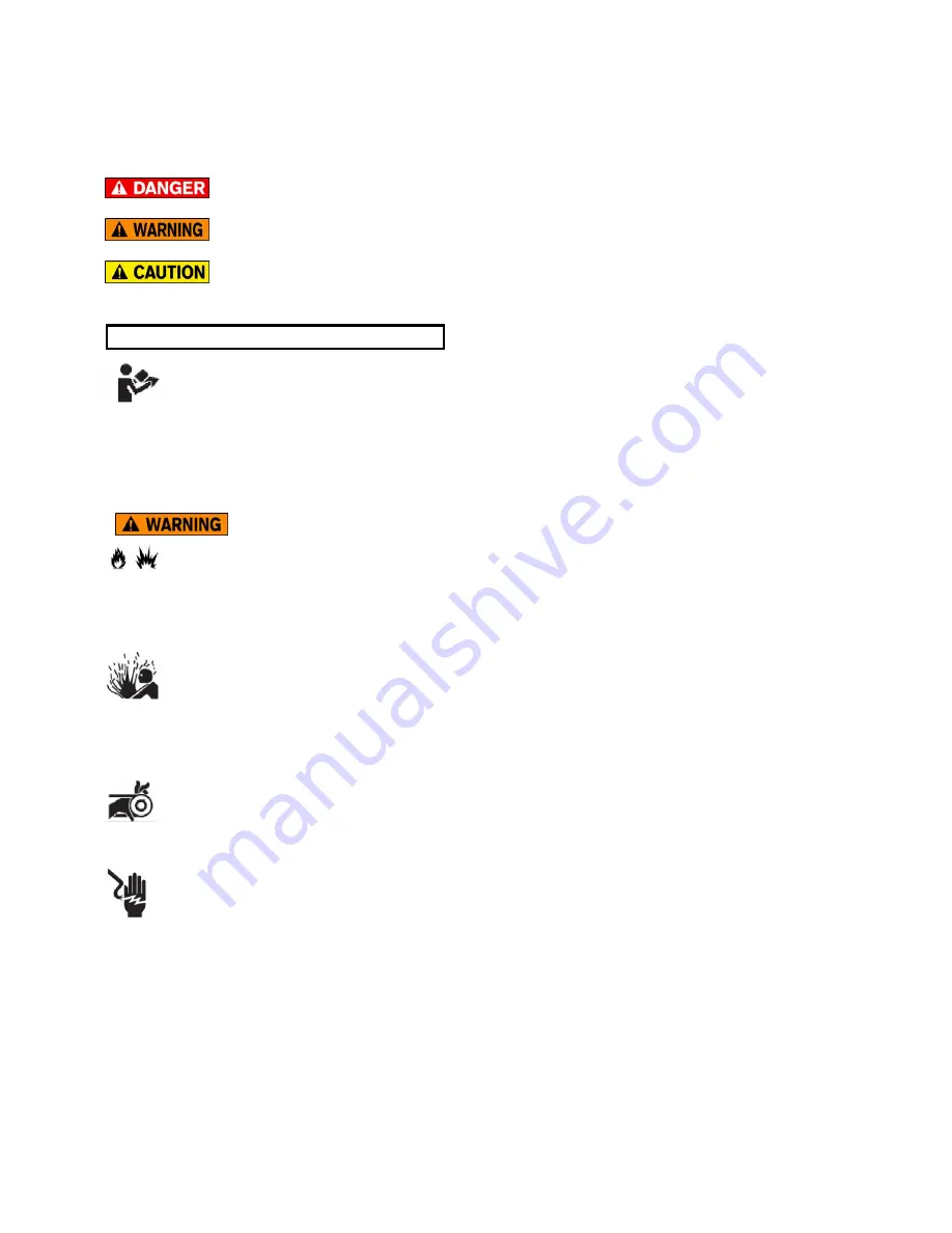
Safety symbols identify important safety messages that alert to the possibility of personal injury or death.  
Review them carefully before operating the unit and before performing maintenance or repairs. Check the rules 
and regulations at your location and identify possible hazards. The appropriate signal word for each message 
has been selected using the following guidelines: 


Danger indicates an immediate and specific hazard, which 

will

 result in 

severe


personal 

injury

 or 

death

 if the proper precautions are not taken.


-


Warning indicates a specific hazard or unsafe practice, which 

could 

result in 

severe 

personal injury

 or 

death

 if proper precautions are not taken.


- Caution indicates a potentially hazardous situation, which 

may

 result in 

minor

 or 

moderate 

injury

 if proper practices are not taken.


____________________________________________________________________________ 

IMPORTANT SAFETY INSTRUCTIONS  


Read and understand the operator’s manual and all safety alerts before 

operating or maintaining your Compressor. Be certain that everyone operating this 
equipment is familiar with the recommended operating and maintenance procedures 
and follows all the safety precautions. Never let children or untrained adults operate 
the machine.


_______________________________________________________________________________ 


RISK OF FIRE OR EXPLOSION


Never spray flammable liquids in a confined area.  It is normal for the motor and pressure switch to produce 
sparks while operating.  If sparks come into contact with vapors from gasoline or other flammable solvents, 
they may ignite, causing a fire or an explosion.  Always operate the compressor in a well-ventilated area as far 
from spray area as possible. 


RISK OF BURSTING


Air under pressure will cause injury, death or property damage. Do not exceed pressure rating. Safety relief 
valve settings must not be changed, check regularly for proper operation. Do not weld, drill or modify 
compressor tank; it can severely impair tank strength and cause extremely hazardous conditions. Any 
adjustment by user will void the warranty. 


RISK OF INJURY


Do not operate with belt guard removed. Wait for all moving parts to stop before removing belt guard for 
compressor servicing. Belt guard must be fastened in place before starting the compressor. 


RISK OF ELECTRICAL SHOCK


All electrical enclosures, cables, wiring and components must be installed and grounded in accordance with 
national and local electrical code. 
 

ALL WIRING MUST BE DONE BY A LICENSED ELECTRICIAN.


Failure to comply could result 

in personal injury or damaged components.

Summary of Contents for 10E-2-120H-1-230

Page 1: ...scharge System 9 3 2 Assembly 11 3 3 Pre Operation Checklist 11 3 4 Break in and Startup 12 3 5 Daily Starting Checklist 12 4 MAINTENANCE 13 4 1 Maintenance Safety 13 4 2 Servicing Intervals 13 4 3 Pu...

Page 2: ...e and troubleshooting information contained within this Operator s Manual WARRANTY PARTS SERVICE If you experience any problems and need assistance or parts and repair service please contact Princess...

Page 3: ...a SK S4P 3V7 N Surtees Ph 306 787 4522 Fax 306 787 9273 Department of Labour Manpower Mechanical Engineering 500 401 York Ave Winnipeg MB R3C 0P8 I W Mault Ph 204 945 3373 Fax 204 948 2309 Technical S...

Page 4: ...Whitehorse Yukon Y1A 2C6 Dan Price Government of the Northwest Territories Department of Public Services Safety Division Boiler Pressure Vessel Branch 4916 49 th Street Northway Building Yellowknife...

Page 5: ...ety precautions Never let children or untrained adults operate the machine _______________________________________________________________________________ RISK OF FIRE OR EXPLOSION Never spray flammab...

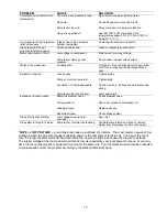
Page 6: ...times RISK TO BREATHING Toxic volatile and corrosive vapors can cause personal injury Provide adequate ventilation Never directly inhale compressed air produced by a compressor It is not suitable for...

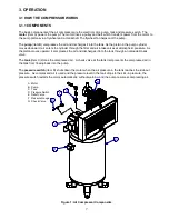
Page 7: ...es at atmospheric pressure As the piston moves upward it compresses the air and discharges it into the tank through an unloader check valve The tank item C stores the compressed air A check valve at t...

Page 8: ...ressure switches provided are pre set at the factory and should not be adjusted WARNING Never exceed the designed pressure for the system or overload the motor beyond the amperage rating on the motor...

Page 9: ...e from entering the tool or device used with the air 4 Shut off Valves Install shut off valves in each drop line to isolate the tool and its accessories for servicing You can also install a bypass lin...

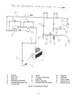
Page 10: ...10 Figure 2 Compressor Air System...

Page 11: ...ed on the electric motor and on the pressure switch or provided with the magnetic starter sold separately Princess Auto cannot by law provide the customer with any additional wiring information 3 3 PR...

Page 12: ...sure 7 Check the operation of controls and system pressure 8 Observe compressor operation closely for the first hour and then frequently for the next 8 hours of operation 9 After the first 8 hours of...

Page 13: ...p oil level b Drain drop legs and traps in air distribution system c Manually operate the pressure relief valves d Give compressor an overall visual inspection and be sure safety guards are in place e...

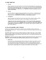
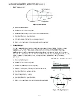
Page 14: ...indicates that condensation is forming in the crankcase This condensation must be drained immediately or the pump may be damaged 4 4 PULLEY ALIGNMENT BELT TENSION Improper pulley alignment and belt te...

Page 15: ...straightedge to the edge of the drive belt dimension E Then measure the distance from the straightedge to the edge of the drive belt again as shown by dimensions F and G Both distances should be the s...

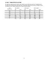
Page 16: ...of all fasteners using the table as a guide Replace hardware with the same strength materials Bolt Diameter in SAE Grade 2 SAE Grade 5 SAE Grade 8 N m ft lbs N m ft lbs N m ft lbs 1 4 8 6 12 9 17 12 5...

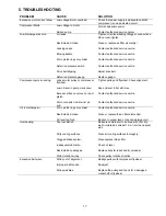
Page 17: ...crankcase Excess carbon on valves on top of piston Worn connector rod at wrist pin end Tighten pulley and flywheel Check alignment Keep oil level full at all times Contact authorized service centre C...

Page 18: ...nadequate Compressor feet are not level Tighten pulley Tighten bolts Check mounting Surface should be level and strong Level with shims Excessive oil consumption Defective breather valve Wrong grade o...

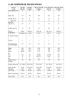
Page 19: ...tage 1 2 2 2 2 Cylinder 3 2 4 4 4 Oil Required fill to center of sight glass 1 6 L 1 5 L 1 9 L 1 9 L 1 9 L Motor ODP ODP ODP ODP ODP RPM 3450 1750 1750 1750 1750 Frame R56HZ 184T 215T 215T 215T Ph 1 1...

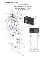
Page 20: ...20 7 ASSEMBLY PART LISTS COMPRESSOR 5 HP 1 STAGE VERTICAL MODEL 5E 1 60V ITEM 8355182...

Page 21: ...051 INSERT B COMP 25 X 125 NPTM 2 17 9255068 TUBE RD NYLON 25 OD X 16 00 LG 1 18 10002560 TAG BREAK IN OIL 1 19 9232141 ELBOW 375 NPT STREET 1 20 9236548 CAP B HEX 375 NPTF 1 21 10005772 DECAL PAL MAN...

Page 22: ...22 COMPRESSOR 5 HP 2 STAGE VERTICAL MODEL 5E 2 80V ITEM 8346645...

Page 23: ...1 ELBOW 375 NPT STREET 1 19 9236548 CAP B HEX 375 NPTF 1 20 3860013 BELT B70 2 21 10005772 DECAL PAL MANUFACTURING 1 22 10000808 DECAL WARNINGS COMPRESSORS 1 23 9161308 DECAL MAINTENANCE INSTRUCTIONS...

Page 24: ...24 COMPRESSOR 10 HP 2 STAGE HORIZONTAL MODEL 10E 2 120H 3 230 ITEM 8346652...

Page 25: ...REET 1 16 9224304 NIPPLE B 375 NPT X 6 00 LG 1 17 9236118 RELIEF VALVE 200 210 PSI 1 18 10005772 DECAL PAL MANUFACTURING 1 19 10000808 DECAL WARNING 1 20 9161365 DECAL DRAIN WATER 1 21 9161308 DECAL M...

Page 26: ...26 COMPRESSOR 10 HP 2 STAGE HORIZONTAL MODEL 10E 2 120H 1 230 ITEM 8347767...

Page 27: ...MANUFACTURING 1 16 9161340 DECAL ARROW 1 17 9224304 NIPPLE B 375 NPT X 6 00 LG 1 18 9330077 ELBOW B 375 NPT STREET 1 19 9236548 CAP B HEX 375 NPTF 1 20 9235250 BOLT HEX SER 312 18UNC X 75 LG 1 21 100...

Page 28: ...28 COMPRESSOR 10 HP 2 STAGE HORIZONTAL MODEL 10E 2 120H 3 575 ITEM 8347783...

Page 29: ...NUFACTURING 1 16 9161340 DECAL ARROW 1 17 9224304 NIPPLE B 375 NPT X 6 00 LG 1 18 9330077 ELBOW B 375 NPT STREET 1 19 9236548 CAP B HEX 375 NPTF 1 20 9235250 BOLT HEX SER 312 18UNC X 75 LG 1 21 916081...

Page 30: ...30 8 PUMP PART LISTS PUMP 10001977 LPW6548ALHI USED ON ITEM 8355182...

Page 31: ...31 PUMP 10001977 LPW6548ALHI USED ON ITEM 8355182...

Page 32: ...32 PUMP 10002222 LP205CT USED ON ITEMS 8346645...

Page 33: ...33 PUMP 10002222 LP205CT USED ON ITEMS 8346645...

Page 34: ...34 PUMP 10002332 LP210CT USED ON ITEMS 8346652 8347767 8347783...

Page 35: ...35 PUMP 10002332 LP210CT USED ON ITEMS 8346652 8347767 8347783...

Reviews: