background image

Note:

 The purpose of a temperature-pressure relief valve 

is to prevent excessive temperatures and pressures in 
the storage tank. The T&P valve is not intended for the 
constant relief of thermal expansion. A properly sized 
thermal expansion tank must be installed on all closed 
systems to control thermal expansion, see “Closed Water 
Systems” and “Thermal Expansion” section.

 Temperature-Pressure Relief Valve and Pipe 
Insulation

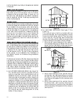
The T&P valve installed on this water heater is covered by 
insulation to minimize heat loss. The insulation has a hole 
on the bottom side to accommodate the valve outlet and 
allow for the piping connection. Do not restrict the outlet 
opening of the T&P valve.

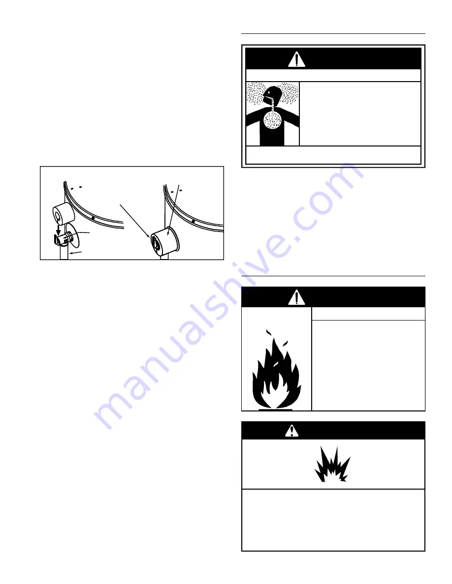
T&P Relief Valve

T&P Relief Valve
Drain Line

Manual Relief Lever

T&P Relief Valve Insulation
(Outlet opening on underside)

Figure 24.  

Locate the temperature and pressure relief valve on the 
water heater (also known as a T&P relief valve). See 
Figure 24.
1.  Locate the slit running the length of the T&P relief 

valve insulation.

2.  Spread the slit open and 

fi

 t the insulation over the T&P 

relief valve. See Figure 24. Apply gentle pressure to 
the insulation to ensure that it is fully seated on the T&P 
Relief Valve. Once seated, secure the insulation with 
duct tape, electrical tape, or equivalent. IMPORTANT: 
The insulation and tape must not block the discharge 
opening or hinder access to the manual relief lever 
(Figure 24). Ensure a discharge pipe is installed into 
the T&P valve discharge opening per the instructions 
in this manual.

3.  Locate the hot water (outlet) & cold water (inlet) pipes 

to the water heater.

4.  Locate the slit running the length of a section of pipe 

insulation.

5.  Spread the slit open and slip the insulation over the 

cold water (inlet) pipe. Apply gentle pressure along 
the length of the insulation to ensure that it is fully 
seated around the pipe. Also, ensure that the base 
of the insulation is 

fl

 ush with the water heater. Once 

seated, secure the insulation with duct tape, electrical 
tape, or equivalent.

6.  Repeat steps 5 and 6 for the hot water (outlet) pipe.
7.  Add additional sections of pipe insulation as needed.

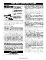
 HIGH  ALTITUDE  INSTALLATION

Breathing carbon monoxide can cause brain damage or death.

Always read and understand instruction manual.

 For operation above 10,100 ft. 

(3,079 metres) a high altitude 
orifice must be installed.

 Contact a qualified installer or 

service agency.

Breathing Hazard - Carbon Monoxide Gas

WARNING

This heater is approved for operation up to 10,100 feet 
without alteration.

Failure to replace standard ori

fi

 ce with a high altitude 

ori

fi

 ce when installed above 10,100 feet could result 

in improper and inef

fi

 cient operation of the appliance, 

producing carbon monoxide gas in excess of safe limits, 
which could result in serious injury or death. Contact 
your gas supplier for any speci

fi

 c changes which may be 

required in your area.

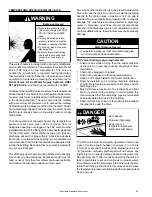
 GAS  PIPING

• 

Do not use water heater with 

any gas other than the gas 
shown on the rating plate.

• 

Excessive pressure to gas 

control valve can cause serious 
injury or death.

• 

Turn off gas lines during 

installation.

• 

Contact qualified installer or 

service agency.

Fire and Explosion Hazard

WARNING

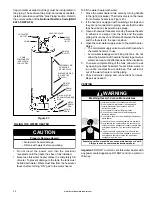
Explosion Hazard

Have a qualified technician make sure that the L.P. 
gas operating pressure does not exceed 13" water 
column.
Failure to do so can result in death, explosion, or 
fire.

WARNING

24 www.americanwaterheater.com 

Summary of Contents for POWER VENTED GAS Models

Page 1: ...REQUIRED POWER VENTED GAS MODELS WITH HOT SURFACE IGNITION NOT FOR USE IN MANUFACTURED MOBILE HOMES For Your Safety AN ODORANT IS ADDED TO THE GAS USED BY THIS WATER HEATER ALL TECHNICAL AND WARRANTY...

Page 2: ...itude Installation 24 Gas Piping 24 Sediment Traps Dirt Leg 25 Filling The Water Heater 26 Venting 26 Termination Clearances Sidewall Power Vent 27 Blower Assembly Installation 28 Installation Of Vent...

Page 3: ...rn of potential exposure to such substances This product contains a chemical known to the State of California to cause cancer birth defects or other reproductive harm This appliance can cause low leve...

Page 4: ...GENERAL SAFETY 4 www americanwaterheater com...

Page 5: ...are heavier than air 3 go a long way on the floor and 4 can be carried from other rooms to the the electodes by air currents Flammable Vapors FLAMMBLE DANGER Breathing carbon monoxide can cause brain...

Page 6: ...is manual contains instructions for installation operation and maintenance of the gas fired water heater It also contains warnings throughout the manual that you must read and be aware of All warnings...

Page 7: ...tally vented gas fueled heating appliance or equipment The sign shall read in print size no less than one half 1 2 inch in size GAS VENT DIRECTLY BELOW KEEP CLEAR OF ALL OBSTRUCTIONS INSPECTION The st...

Page 8: ...REQUIREMENTS 1 CONNECT ELECTRONICALLY CONTROLLED TIMER TO AN ALL BRONZE PUMP PUMP MUST ACTIVATE EVERY 6 HOURS FOR 60 SECONDS TURN PUMP TIMER OFF BEFORE CLOSING PIPING LOOP SHUT OFF VALVE 2 ALL WATER...

Page 9: ...g see Figure 6 26 Rubber Coupling see also Figure 6 27 Gear Clamp see also Figure 6 28 Flue Collector 29 Hot Water Outlet Nipple 30 Anode under cap 31 Control Harness 32 Flexible Manifold Tube see Fig...

Page 10: ...has 120 VAC In operation See Planning The Vent System Condensate and Blower Assembly Installation for more information REPLACEMENT PARTS AND DELIMING PRODUCTS Replacement parts and recommended delime...

Page 11: ...9001262 CAN BE ORDERED THROUGH THE MANUFACTURER NOTE THE T P VALVE DISCHARGE PIPE MUST BE PIPED DIRECTLY TO THE DRAIN OR EXTERNAL TO THE BUILDING MASSACHUSETTS INSTALL A VACUUM RELIEF IN COLD WATER L...

Page 12: ...Figure 9 or at hot water taps to further reduce system water temperature Mixing valves are available at plumbing supply stores Consult a Qualified Installer or Service Agency Follow mixing valve manu...

Page 13: ...r the correct electrical connections After making all electrical connections completely fill the tank with water and check all connections for leaks Open the nearest hot water faucet and let it run fo...

Page 14: ...e vapors before they enter the combustion chamber this water heater is equipped with a flammable vapor sensor FVS It is a chemical absorption based sensor that is connected to the gas control thermost...

Page 15: ...an adequate drain The pan must have a maximum depth of 1 75 Water heater life depends upon water quality water pressure and the environment in which the water heater is installed Water heaters are so...

Page 16: ...very direction or if the appliance is installed in an alcove or closet the entire floor must be covered by the panel Failure to heed this warning may result in a fire hazard Clearance for servicing Ad...

Page 17: ...safe operation an adequate supply of fresh uncontaminated air for combustion dilution and ventilation must be provided Note Contaminated or dusty air may cause build up on the blower wheel resulting i...

Page 18: ...igerants swimming pool chemicals calcium and sodium chloride water softener salt waxes bleach and process chemicals are typical compounds which are potentially corrosive A ALL AIR FROM INSIDE BUILDING...

Page 19: ...free area Louvers and grilles shall be fixed in the open position or interlocked with the equipment so that they are opened automatically during equipment operation 7 Special Conditions Created by Me...

Page 20: ...ing on thermostat read Operating The Temperature Control System section in this manual This water heater should not be connected to any heating systems or components previously used with a non potable...

Page 21: ...loss 7 If the local jurisdiction requires a back flow preventer in the cold water line an expansion tank of adequate size must be installed 8 Combo Heating Systems require higher water temperatures th...

Page 22: ...d systems to control the harmful effects of thermal expansion Contact a plumbing service agency or your retail supplier regarding the installation of a thermal expansion tank Note To protect against u...

Page 23: ...over 30 feet or use of more than four elbows can cause restriction and reduce the discharge capacity of the valve No valve or other obstruction is to be placed between the T P valve and the tank Do no...

Page 24: ...eater 4 Locate the slit running the length of a section of pipe insulation 5 Spread the slit open and slip the insulation over the cold water inlet pipe Apply gentle pressure along the length of the i...

Page 25: ...ape compatible with propane Leak test before operating heater Disconnect gas piping and shut off valve before pressure testing system Fire and Explosion Hazard WARNING Use pipe joint compound or Teflo...

Page 26: ...etween the heater and the faucets are the open position 4 Open the cold water supply valve to the water heater Notes The cold water supply valve must be left open when the water heater is in use Avoid...

Page 27: ...or to side of opening 1 foot above opening D Vertical clearance to ventilated soffit located above the terminal within a horizontal distance of 2 ft from the center line of the terminal 12 in K Clear...

Page 28: ...e To start off with an elbow a short section of the straight pipe must be cut and glued into the end of the elbow that will mount on the discharge boot INSTALLATION OF VENT SYSTEM Before beginning ins...

Page 29: ...nnection is required and is available through your supplier Optional wall plates that fit the polypropylene venting are also available through your supplier Carefully inspect the entire venting system...

Page 30: ...use approved material All venting material and components must be joined with the approved primer cleaner and solvent cement Do not common vent this heater with any other appliance During operation th...

Page 31: ...g to attach the venting to the blower and a 3 45 vent termination elbow Supplied with this heater are several vent termination screens see Figure 31 Figure 32 Installed in the vent termination elbow t...

Page 32: ...ong Sweep Long Radius Notes 1 Use long radius elbows where possible Minimum distance between 90 elbows should be 6 wherever possible 2 Venting systems may use a maximum of five 5 90 elbows 3 Use prope...

Page 33: ...e vent piping through this hole and secure into position Connect the vent pipe to the end termination elbow as shown in Figure 34 thru Figure 36 10 Dry fit all vent pipes elbows connectors and fitting...

Page 34: ...ber coupling Check that there is no stress on the connection or the vent piping that may be caused by twisting or bending 6 Tighten the upper clamp so that the vent piping is firmly secured in the cou...

Page 35: ...u have any questions about the application or installation of PVC and CPVC pipe Take the time and effort to do a professional job Shortcuts will only cause you problems and delays in start up By far t...

Page 36: ...oper interfacing of the pipe end and the fitting socket bottom This can be accomplished with a miter box saw or wheel type cutter Wheel type cutters are not generally recommended for larger diameters...

Page 37: ...g socket Avoid puddling Apply a second coat of cement to the pipe end Cans of cement and primer should be closed at all times when not in use to prevent evaporation of chemicals and hardening of cemen...

Page 38: ...cated as close to gas piping and vent pipe system as possible 2 Located indoors and in a vertical position Protected from freezing temperatures 3 Proper clearances from combustible surfaces maintained...

Page 39: ...ht manually 6 Wait five 5 minutes to clear out any gas If you then smell gas STOP Follow B in the safety information above on this label If you don t smell gas go the next step 7 Turn on all electric...

Page 40: ...ing certain temperature water at the hot water tap then you must take special precautions In addition to using the lowest possible temperature setting that satisfies your hot water needs a means such...

Page 41: ...s HOT 120 More than 5 minutes LOW 110 Normal shower temp VAC 70 N A Table 4 Note The temperatures indicated are approximates The actual temperature of the heated water may vary The Vacation Setting VA...

Page 42: ...or your retail supplier regarding the installation of a thermal expansion tank Closed water systems See Closed Water Systems section elsewhere in this manual Smoke odor It is not uncommon to experien...

Page 43: ...xplosive To prevent the possibility of injury under these conditions it is recommended that the hot water faucet located farthest away be opened for several minutes before any electrical appliances wh...

Page 44: ...l the local gas utility to correct the problem and clean or replace the flue and venting before resuming operation of the water heater BLOWER MAINTENANCE Inspect the top of the heater and around the v...

Page 45: ...BLOWER FLUE COLLECTOR HOOD 11 32 NUTS MOUNTING PLATE GEAR CLAMP VENT PIPE MOTOR Figure 49 BURNER OPERATION AND INSPECTION Flood damage to a water heater may not be readily visible or immediately dete...

Page 46: ...tificially softened water can be exceedingly corrosive because the process substitutes sodium ions for magnesium and calcium ions The use of a excessively soft water may decrease the life of the water...

Page 47: ...ANGER It is recommended that the temperature pressure relief valve be checked to ensure it is in operating condition at least once a year When checking the temperature pressure relief valve operation...

Page 48: ...ater is going to be shut down and drained for an extended period the drain valve should be left open with hose connected allowing water to terminate to an adequate drain 6 Close the water heater drain...

Page 49: ...temperature pressure relief valve may be due to thermal expansion or high water pressure in your area E The temperature pressure relief valve may be leaking at the tank fitting F Water from a drain va...

Page 50: ...Snorkel 20 Combo Heating System Supply Outlet Optional 21 Blower with Power Cord see also Figure 61 22 Air Switch inside box see Figure 61 23 Junction Box see Figure 61 24 Junction Box Cover see Figu...

Page 51: ...gas and Propane main burner with igniter assembly for 60k to 75k Btu hr models Flare Nut Figure 59 17 Figure 60 25 23 24 22 5 26 27 21 Figure 61 Notes Natural gas models have Right hand thread Propan...

Page 52: ...gas control valve thermostat 1 Turn temperature knob to lower setting 2 Replace the gas control valve thermostat SLOW HOT WATER RECOVERY 1 Insufficient air flue blockage 2 Low gas pressure 3 Orifice...

Page 53: ...e see rating plate 5 Clean locate source and correct 6 Replace gas control valve thermostat 7 Provide fresh air ventilation UNABLE TO LIGHT THE BURNER 1 Air in gas line 2 Pressure switch 3 Blocked exh...

Page 54: ...rease ventilation to lower room temperature 4 Install correct orifice RESETTING THE HEATER CONTROL Soft lockouts as diagnosed by the system error codes require the gas control to be reset To reset the...

Page 55: ...the problem before attempting corrective action See also Flammable Vapor Sensor LED Flash Sequence Control Status Short flash once every four seconds IDLE no call for heat no fault conditions Heartbea...

Page 56: ...This page intentionally left blank May be used for notes or to record other installation information 56 www americanwaterheater com...

Page 57: ...This page intentionally left blank May be used for notes or to record other installation information www americanwaterheater com 57...

Page 58: ...urnish the Owner with a replacement for the defective part s This warranty is limited to one replacement component part for each original part 3 Return of Defective Water Heater and Component Parts Ma...

Page 59: ...and installing a new water heater or component part s c Any material required to complete and or permits required for installation of a new water heater or replacement part s and d All costs necessary...

Page 60: ...American Water Heaters 500 Princeton Road Johnson City TN 37605 Phone 800 999 9515 Fax 800 999 5210 www americanwaterheater com Copyright 2013 American Water Heater Company All rights reserved...

Reviews: