Operator's Manual
4-Cycle Cultivator
866-443-2576
12
ADJUSTING WHEELS AND DRAG STAKE
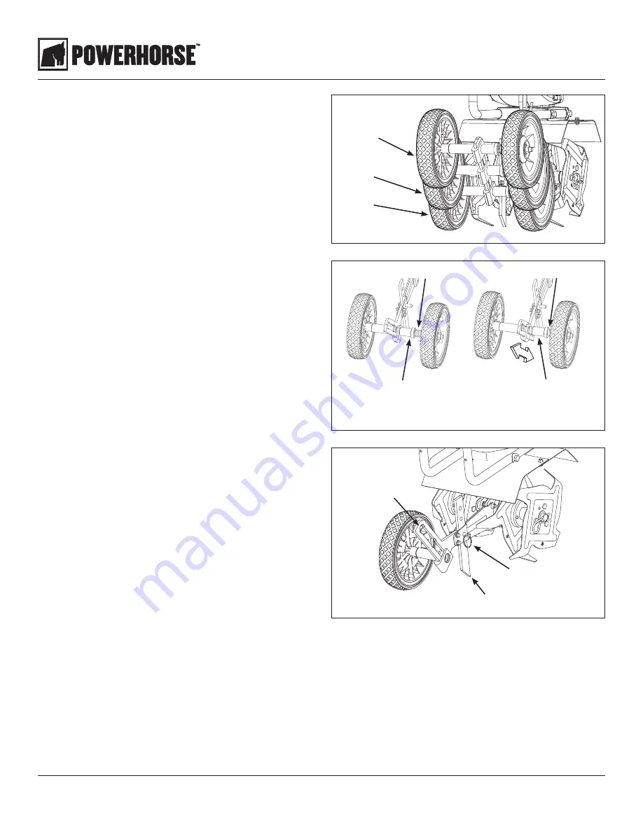
The wheels on the cultivator can be adjusted to one of three
positions. The LOW wheel position is used for transporting the
cultivator across a smooth level surface while the engine is not
running. The HIGH and HIGHEST wheel positions are used when
cultivating in soil and help stabilize the unit when cultivating at
different depths. (SEE FIGURE 5)
To adjust wheels up or down (SEE FIGURES 6 AND 7):
1. Pull the locking metal sleeve against the spring, away from the
vertical guide until it releases from one of the three notched
positions in the vertical guide.
2. Slide the wheel set up or down to the desired position, and
release the locking metal sleeve until it locks into desired
notch in the vertical guide.
The drag stake is used to help regulate cultivating depth and
control the cultivator from leaping forward during operation.
Resistance to forward motion is greatest when the drag stake is
set in its lowest position allowing for deeper cultivation.
To adjust the drag stake (SEE FIGURE 7):
1. Pull the pin out of the drag stake mount hole.
2. Position the drag stake so the pointed tip is directed
downward.
3. Insert the pin into the hole that achieves desired depth.
FIGURE 5
HIGHEST position
HIGH position
LOW position
drag stake
vertical guide
detent pin
locking metal sleeve
(LOCKED position)
expanded spring
FIGURE 7
compressed spring
FIGURE 6
locking metal sleeve
(UNLOCKED position)
TINE REMOVAL AND INSTALLATION
To Remove Tines (SEE FIGURE 8)
1. Remove the hairpins from each end of the tine shaft.
2. Slide the four tines off the shaft.
To Install Tines
1. First slide the inside tines onto each end of the tine shaft.
One inside tine is stamped with a B and the other is
stamped with a C.
2. Slide the outside tine A and tine D onto each end of the
shaft next. The tines should be installed in the correct order
so that they are positioned left to right A, B, C, D, as viewed
from the user’s position on the cultivator. Make sure that
the hub collars on both the right and left pairs of tines face
each other so that there is adequate spacing between the
tine blades. SEE FIGURE 8
3. Insert the hairpins into the holes at each end of the tine
shaft to lock the tines into place.
NOTE: Tines can be reversed so the pointed tip of the tines
are directed forward - for more aggressive digging. In this
arrangement, tines are positioned left to right D, C, B, A as
viewed from the user’s position


