6
2.
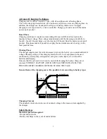
Connect the negative battery cable to terminal marker –BAT and open the entry of the
upper case to tighten it with screws.
3.
Do the same for batteries number 2 and 3 for +BTA 2 and +BTA 3. For a 3 outputs
charger, refer to the table below to choose conductor section.
BTS3
BTS2
BTS1
-BAT
+BAT1
+BAT2
+BAT3
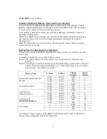
Battery fuse board:
Model No.
12V/20A
12V/40A
12V/60A
FUSE Atofuse (car)
1 x 25A
2 x25A
2 x 30A
Model No.
24V/15A
24V/30A
24V/50A
FUSE Atofuse (car)
1 x 15A
2 x15A
2 x 30A
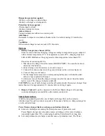
WARNING:
Check carefully the tightness of the battery connections to the charger (risk
if not properly tightened).
Power Master will not take charge of damage caused by a
bad tightness of connections.
Don’t connect a charge distributor on an Power Master charger, 1 or 3 outputs.
4.
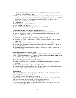
Put the AC plug in the rear panel. The charger operates on sector 90V to 250 Vac -
50/60 Hz. Use preferably cable H07rn-F with 3 conductors. Earth lead to be
connected to the terminal on the unit.
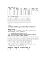
Length 5m 10m 15m Sector
flex
section
(5m)
Current
220V
110V
Puissance
(W)
30A 6
mm
2
10 mm
2
16 mm
2
1.5 mm
2
2.5
mm
2
750
40A 10
mm
2
16 mm
2
25 mm
2
1.5 mm
2
1.5
mm
2
500
50A 16
mm
2
25 mm
2
35 mm
2
1.5 mm
2
2.5
mm
2
1200
60A 25
mm
2
25 mm
2
35 mm
2
1.5 mm
2
2.5
mm
2
750
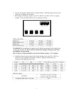
Main fuse board:
Model No.
12V/20A, 12V/40A, 12V/40A,
24V/15A, 24V/30A, 24V/50A
Temporized glass fuse 6.3x32mm
16A


