background image


8

FUSE OPEN

Fuse is broken.   


Switches Section (4 Battery Types and 1 User Define) 

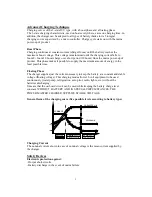
The great advances realized by manufacturers of batteries put at the disposal of users 
batteries without maintenance, so it means a certain tranquillity for the user but impose, 
however on the charger system, an exacting precision. 
Every battery is designed according to particular technology and therefore calls for a 
particular charging curve.   
With Power Master battery charger, you can achieve this perfect match between battery 
and charger using a switch, which is simply positioned according to the required, 
charging curve.   

Note: 

Do indicate the type of your battery when buying the charger, and position the 

switch correctly before use.   
 

Instruction of Charging Curve Selection 

The user can very easily adapt the Power Master charger to the type of battery by rotate 
switch used. 
To modify configuration carryout the following steps: 
STEP 1: Disconnect charger from the mains. To avoid short-circuit, disconnect the             
              batteries. 
STEP 2: According to 4 different battery types and desired charge current (30%, 70% and                
       100%), choose the rotate switch from 1 to C. If the used battery is not in 4 listed       
       battery types, User Define is available.  
 

Battery Type 

U Boost 

U Float 

Charge 

Current 

Rotate 

Switch 

14.4V 13.5V 100%  1 
14.4V 13.5V  70% 

Sealed lead, maintenance-free 
gel type 

14.4V 13.5V  30% 

14.2V 13.8V 100%  4 
14.2V 13.8V  70% 

Classical lead open 

14.2V 13.8V  30% 

14.6V 14.0V 100%  7 
14.6V 14.0V  70% 

Lead calcium   
(standard charge ) 

14.6V 14.0V  30% 

16.0V 13.8V 100%  A 
16.0V 13.8V  70% 

Lead calcium * 

DEEP DISCHARGE 

16.0V 13.8V  30% 


 100% D 


 70% E 

User Define 


 30% F 

 
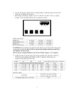
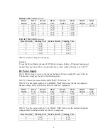
User Define: Use the switches of the BOOST VOLTAGE and FLOAT VOLTAGE to 
choose desired voltages from the following tables.   


Summary of Contents for PM-SBC-1524

Page 1: ...SWITCH MODE BATTERY CHARGER MICROPROCESSOR SYSTEM USER MANUAL FOR ALL PATTERNS 1 AND 3 OUTPUTS ...

Page 2: ...e 3 Safety Devices 3 Options 4 Safety Instruction 4 Installation 5 Front Panel 7 LED Indicators 7 Switches Section 4 Battery Types and 1 User Define 7 Instruction of Charging Curve Selection 8 DC Power Supply 9 BTS Remote Control 10 Trouble Shooting Guide 10 Specification 11 ...

Page 3: ... the market to allow the battery to be connected and used constantly while still offering a real BOOST high voltage charge over short period The charger switches back to top up mode automatically In accordance with EC standards the Power Master Battery charger is fitted with a PFC Power Factor Corrector which limit peak current draw from the input power required from the generator or Mains supply ...

Page 4: ...f energy in the least possible time Floating Phase The charger supplies just the current necessary to keep the battery at a constant and stable voltage floating voltage This charging mode allows 12 volt equipment to be used continuously water pump refrigeration auto pilot radio lights etc without the batteries discharging It means that the on board circuit can be used while keeping the battery cha...

Page 5: ... A 4 Connect charger to the mains 5 Fix the temperature sensor s on corresponding battery ies with double sided adhesive tape supplied with sensor To disconnect sensor from the charger charger must be disconnect from the mains before even if the charger indicates a default CAUTION In case of fault charger switches off automatically Disconnect charger from mains then wait for approximately 10 minut...

Page 6: ...ed on any installation where there is a danger of electrolytic effects z Regulations require the presence of a battery cut out on the output pole and on the output pole Precautions Regarding Lightning Strike In geographic zones exposed to a high risk of lightning strikes it may be recommended fitting a lightning conductor on the inlet side of the charger Power Master will not take charge of damage...

Page 7: ... risk if not properly tightened Power Master will not take charge of damage caused by a bad tightness of connections Don t connect a charge distributor on an Power Master charger 1 or 3 outputs 4 Put the AC plug in the rear panel The charger operates on sector 90V to 250 Vac 50 60 Hz Use preferably cable H07rn F with 3 conductors Earth lead to be connected to the terminal on the unit Length 5m 10m...

Page 8: ... for 24 system during more than 5 minutes charger shuts down To restart the charger disconnect the mains wait few minutes and reconnect the charger on mains Over Voltage Battery overcharge Ubat 16V for 12V system and 32V for 24V system If Ubat 16V for 12V system and 32V for 24V system during more than 5 minutes charger shuts down To restart the charger disconnect the mains wait few minutes and rec...

Page 9: ...n very easily adapt the Power Master charger to the type of battery by rotate switch used To modify configuration carryout the following steps STEP 1 Disconnect charger from the mains To avoid short circuit disconnect the batteries STEP 2 According to 4 different battery types and desired charge current 30 70 and 100 choose the rotate switch from 1 to C If the used battery is not in 4 listed batte...

Page 10: ... type to be 5 DC Power Supply Power Master charger can not only charge the battery but also supply DC power directly The desired voltage can be set by the following steps STEP 1 Choose the rotate switch of BATTERY TYPE to be 0 STEP 2 Use the rotate switch 0 F of BOOST VOLTAGE to set the first two digits of desired voltage Refer to the below table for what 0 F represents Rotate Switch Boost Volt Ro...

Page 11: ...oltage but a max intensity One or several elements of the battery present a short circuit Check that there s no increase of battery temperature Battery is almost totally charged Check that the charger is on a floating mode Intensity of charge is too weak 10 Alimentation is too weak Check the input voltage Consumption on the battery during the charge is too important Decrease the consumption Time o...

Page 12: ... the connection of the battery the polarity and the output fuse Problem and Symptoms Possible Cause Solution All LEDS are flashing but the charger doesn t charge DEFAULT Check the battery connections and the connection of display and check the output fuse No LED is lighting when the charger is connected to the main DEFAULT Check the main input the connection of display and the fuses During the cha...

Page 13: ...on Charge Floating Charge Charging Curve Selection By SWITCH for 5 different battery types Classical lead open sealed lead gel lead calcium standard charge lead calcium deep discharge user define Working Temperature 10 45 Storage Temperature 20 70 Protection Feature Against output short circuit battery discharge in the event of mains failure mains input overload battery polarity inversion Protecti...

Page 14: ...By SWITCH for 5 different battery types Classical lead open sealed lead gel lead calcium standard charge lead calcium deep discharge user define Working Temperature 10 45 Storage Temperature 20 70 Protection Feature Against output short circuit battery discharge in the event of mains failure mains input overload battery polarity inversion Protection Options Battery or charger overtemperature Batte...

Reviews: