
4 - ENG
OPERATING INSTRUCTIONS
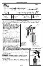
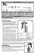
TYPICAL INSTALLATION
This spray gun is shipped from the factory designed for use as a “non-bleeder”, which means you must pull the trigger
on the gun for air to flow through the gun. Non-bleeder operation requires an air compressor that has a storage tank.
Spraying Instructions
1. As a standard practice, drain water from the air
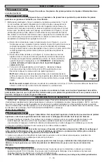
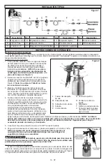
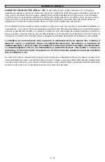
Figure 2
L Air cap nut
Q Pattern control
M Air cap
R Fluid control
N Cup cover
S Trigger
O Cup
T Air inlet port
P Air control
U Female connector
(put
Teflon® tape on the male threads)
compressor tank and air lines prior to use each day
(reference your compressor operators manual for
detailed instructions).
NOTE: Failure to install
appropriate water/oil removal equipment may
result in damage to the spray gun or workpiece
(see
Figure 1).
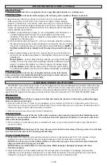
2. Install a 1/4” NPT female connector (included in
accessory kit) into the air inlet port on the tool (see
Figure 2).
Note: Use Teflon® Tape on all threaded
connections.
3. Mix material according to the manufacutrer’s
instructions, adding thinner if needed. Mixture should
be smooth and easily pourable. Lumps or foreign
objects should be removed by straining through a
suitable paint filter or cheesecloth.
4. Fill the cup no more than 3/4 full. Firmly attach the cup
to prevent air leakage. Avoid damage to the sealing
surface of the cup and the gasket—damage to these
parts will cause air leaks and prevent the gun from
spraying properly. If paint leaks around the needle pin
packing gland, tighten the packing gland nut just
enough to stop the leak but not enough to interfere
with movement of the needle pin. Apply light machine
oil to keep the packing soft and help avoid leaks.
NOTE: If using the spray gun for the first time,
fill the paint cup with thinner and spray into a grounded metal waste container to flush the gun and cup
of any impurities that may have accumulated during assembly and shipping.
5. Attach air supply line to 1/4 NPT female connector plug.
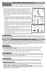
Figure 3
6. Start the compressor and set the regulator to 25-50 PSI.
NOTE: Be sure there is
sufficient hose connected between the gun and air supply to comfortably
reach the work surface.
This spray gun is designed to operate best at pressures
between 25-50 PSI. Never attempt to operate this spray gun at pressures in
excess of 50 PSI.
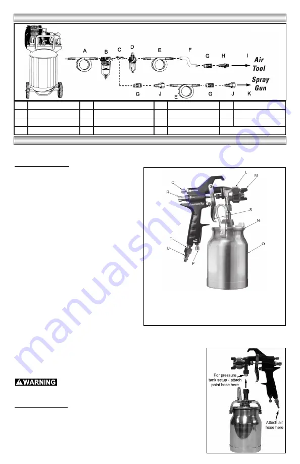
Using a Pressure Tank
When using a pressure tank, unscrew the nut above the cup cover and detach the
entire cup assembly. Attach the paint hose to the spray gun at the location the cup was
attached (see Figure 3). Follow all pressure tank operating instructions when using a
pressure tank.
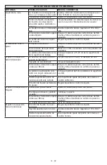
Key
Description
Key
Description
Key
Description
Key
Description
A Air hose
D In-line Oiler
G Quick Coupler
J Female Connector
B In-line Filter
E Air Hose
H Male Connector
K Spray Gun
C Tee Fitting
F Whip Hose
I Air Tool
Figure 1


