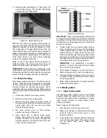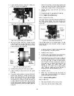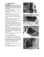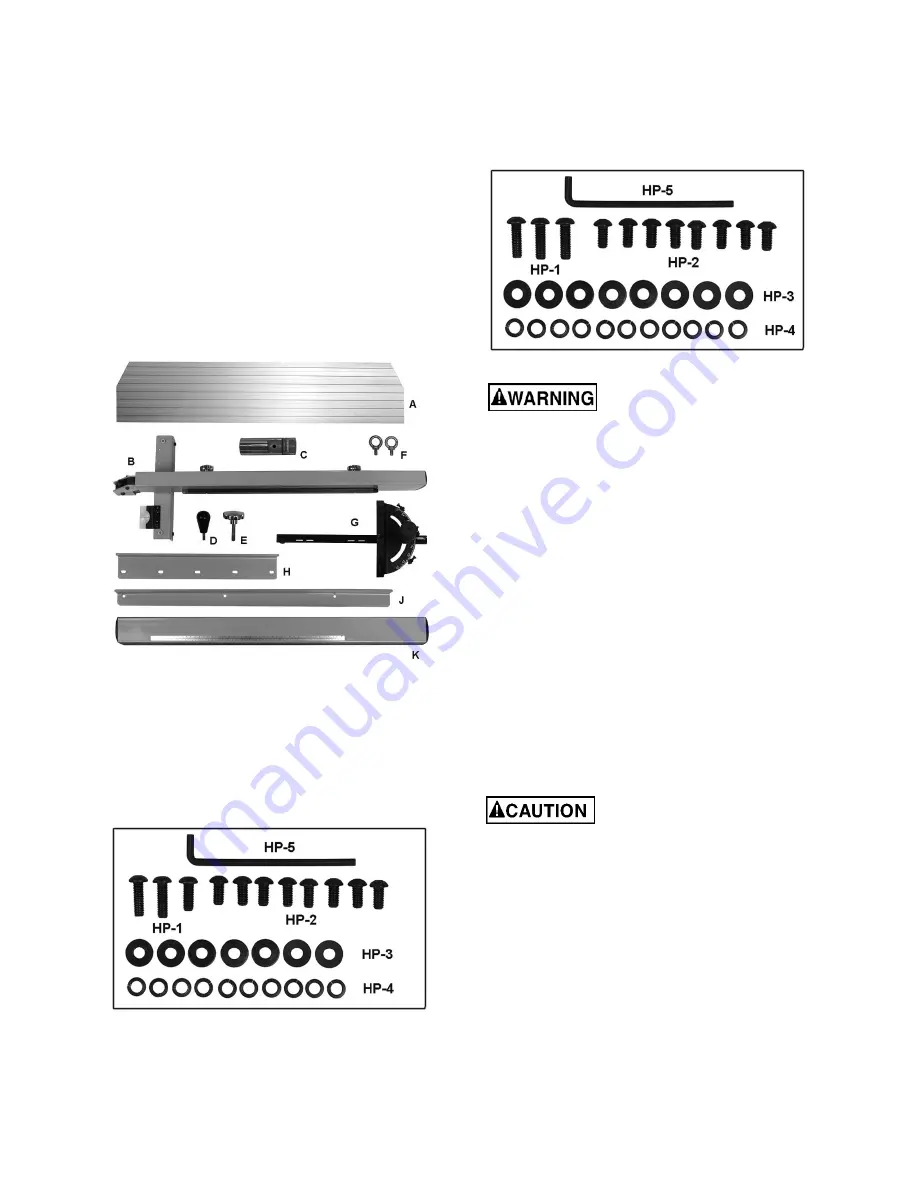
12
8.0
Setup and assembly
8.1
Shipping contents
Carton contents
(see Figure 3)
1 Band saw
1 Fence plate – A
1 Fence body – B
1 Resaw pin – C
1 Fence lever knob – D
1 Resaw pin lock knob – E
2 Eye bolts – F
1 Miter
gauge
–
G
1 Front rail – H
1 Rear rail – J
1 Guide rail – K
Figure 3: contents (items not to scale)
Hardware for PM1800B/2013B
(Figure 3a):
3 Socket head button screws, M8x20 – HP-1
8 Socket head button screws, M8x16 – HP-2
8 Flat washers, M8 – HP-3
11 Lock washers, M8 – HP-4
1 Hex wrench, 8mm – HP-5
Figure 3a
Hardware for PM2415B
(Figure 3b):
3 Socket head button screws, M8x20 – HP-1
8 Socket head button screws, M8x16 – HP-2
8 Flat washers, M8 – HP-3
11 Lock washers, M8 – HP-4
1 Hex wrench, 8mm – HP-5
Figure 3b: (part # PM2415B-HP)
Read and understand all
assembly instructions before attempting
assembly. Failure to comply may cause serious
injury.
8.2
Unpacking
1. Remove all contents from shipping carton. Do
not discard carton or packing material until saw
is assembled and running satisfactorily.
2. Inspect contents. Report any shipping damage
or part shortages to your distributor.
8.3
Spotting the band saw
Tools required for assembly and set up:
Hoist or forklift, with straps/hooks
8mm hex wrench (provided)
Square
Remove all crating and plastic from around
machine. Remove any screws or straps holding
band saw to shipping pallet.
Exercise care when removing
machine from shipping pallet.
Install two eye bolts (F, Figure 2) to top of band saw.
Use hoist or forklift with straps/hooks to remove
machine from pallet. Straps must have a lifting
capacity greater than the band saw weight. Do NOT
place forks or straps directly beneath table or
against handles or levers.
Move band saw to its permanent location, which
should be dry and well lit, with enough space on all
sides to handle long stock or perform routine
maintenance on machine. Make sure floor is able to
support weight of machine. If desired, band saw can
be secured to floor using lag screws (not provided)
through the four holes in the base.
Summary of Contents for 1791257B
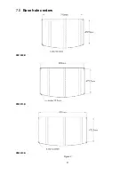
Page 11: ...11 7 0 Base hole centers PM1800B PM2013B PM2415B Figure 2...
Page 35: ...35 17 1 1 Complete Machine with Accessories PM 1800B 2013B Exploded View I...
Page 36: ...36 17 1 2 Complete Machine with Accessories PM 1800B 2013B Exploded View II...
Page 37: ...37 17 1 3 Complete Machine with Accessories PM2415B Exploded View I...
Page 38: ...38 17 1 4 Complete Machine with Accessories PM2415B Exploded View II...
Page 58: ...58 This page intentionally left blank...
Page 59: ...59 This page intentionally left blank...
Page 60: ...60 427 New Sanford Road LaVergne Tennessee 37086 Phone 800 274 6848 www powermatic com...


