background image


5


3.0

  IMPORTANT SAFETY 

INSTRUCTIONS 

WARNING: For your own safety read instruction 
manual before operating Band Saw. 

- Wear eye protection. 

- Do not remove jammed cutoff pieces until blade 
has stopped. 

- Maintain proper adjustment of blade tension, blade 
guides, and thrust bearings. 

- Adjust upper guide to just clear workpiece. 

- Hold workpiece firmly against table. 


1.  Read and understand entire owner's manual 

before attempting assembly or operation. 

2.  Read and understand the warnings posted on 

the machine and in this manual. Failure to 
comply with all of these warnings may cause 
serious injury. 

3. Replace warning labels if they become 

obscured or removed. 

4.  This band saw is designed and intended for use 

by properly trained and experienced personnel 
only. If you are not familiar with the proper and 
safe operation of a band saw, do not use until 
proper training and knowledge have been 
obtained. 

5.  Do not use this band saw for other than its 

intended use. If used for other purposes, 
Powermatic disclaims any real or implied 
warranty and holds itself harmless from any 
injury that may result from that use. 

6.  Always wear approved safety glasses/face 

shield while using this machine. (Everyday 
eyeglasses only have impact resistant lenses; 
they are not safety glasses.) 

7.  Before operating band saw, remove tie, rings, 

watches and other jewelry, and roll sleeves up 
past the elbows. Remove all loose clothing and 
confine long hair. Non-slip footwear or anti-skid 
floor strips are recommended. Do not wear 
gloves. 

8.  Keep work area clean. Cluttered areas and 

benches invite accidents. 

9.  Use proper extension cord. Make sure your 

extension cord is in good condition. When using 
an extension cord, be sure to use one heavy 
enough to carry the current your product will 
draw. An undersized cord will cause a drop in 

line voltage resulting in loss of power and 
overheating. Table 1 shows the correct size to 
use depending on cord length and nameplate 
ampere rating. If in doubt, use the next heavier 
gage. The smaller the gage number, the 
heavier the cord. 

10.  Secure work. Use clamps or a vise to hold work 

when practical. It’s safer than using your hand 
and it frees both hands to operate tool. 

11. 

Disconnect tools before servicing; when 
changing accessories, such as blade, bits, 
cutters and the like. 

12. Direction of feed: Feed work into a blade or 

cutter against the direction of rotation of the 
blade or cutter only. 

13.  Adjust upper blade guides to approximately 1/8” 

above workpiece. 

14. Make sure blade tension, tracking and blade 

guides are all properly adjusted. 

15. Make relief cuts where possible, when cutting 

curved stock. 

16. When feeding small work pieces into blade, 

always use push stick, fixture, or similar device 
to keep hands at a safe distance. 

17.  Hold stock firmly and flat against table. 

18. Wear ear protectors (plugs or muffs) during 

extended periods of operation. 

19. 

WARNING: Drilling, sawing, sanding or 
machining wood products generates wood dust 
and other substances known to the State of 
California to cause cancer. Avoid inhaling dust 
generated from wood products or use a dust 
mask or other safeguards to avoid inhaling dust 
generated from wood products.  

20. Wood products emit chemicals known to the 

State of California to cause birth defects or 
other reproductive harm. (California Health and 
Safety Code Section 25249.6) 

21.  Do not operate this machine while tired or under 

the influence of drugs, alcohol or any 
medication. 

22. Make certain switch is in OFF position before 

connecting machine to power supply. 

23.  Make certain machine is properly grounded. 

24. Do not back stock out of blade while blade is 

running. 

25.  Remove adjusting keys and wrenches. Form a 

habit of checking to see that keys and adjusting 
wrenches are removed from the machine 
before turning it on.  


Summary of Contents for 1791257B

Page 1: ...Manual 18 20 24 inch Band Saws Models PM1800B PM2013B PM2415B PM2013B shown Powermatic 427 New Sanford Road LaVergne Tennessee 37086 Part No M 1791800B Ph 800 274 6848 Revision B 02 2018 www powermat...

Page 2: ...a product requires further inspection the Technical Service representative will explain and assist with any additional action needed Powermatic has Authorized Service Centers located throughout the Un...

Page 3: ...connections 16 9 1 Single phase connections 16 9 2 Three phase connections 16 9 3 Grounding instructions 16 9 4 Extension cords 17 10 0 Adjustments 17 10 1 Table tilt 17 10 2 90 table stop 17 10 3 In...

Page 4: ...d View 45 17 4 2 Upper Wheel Sliding Bracket Assembly Part List 45 17 5 1 Brake Linkage Assembly Exploded View 46 17 5 2 Brake Linkage Assembly Parts List 46 17 6 1 Lower Blade Guide Support Assembly...

Page 5: ...cause a drop in line voltage resulting in loss of power and overheating Table 1 shows the correct size to use depending on cord length and nameplate ampere rating If in doubt use the next heavier gage...

Page 6: ...e the right tool at the correct speed and feed rate Do not force a tool or attachment to do a job for which it was not designed The right tool will do the job better and more safely 34 Use recommended...

Page 7: ...gs or after market accessories choice of stock etc Additional knowledge can be obtained from experienced users or trade articles Whatever accepted methods are used always make personal safety a priori...

Page 8: ...se of motor and electricals Motor type totally enclosed fan cooled induction split phase start Horsepower 5 HP Phase Three Voltage 2 230 460V Cycle 60Hz Listed FLA full load amps 15 7 5A Starting amps...

Page 9: ...164mm Stand footprint PM1800B 31 1 2 L x 20 3 8 W x 2 H 800 x 518 x 51 mm Stand footprint PM2013B 33 1 2 L x 20 3 8 W x 2 H 851 x 518 x 51 mm Stand footprint PM2415B 37 1 2 L x 20 3 8 W x 2 H 956 x 51...

Page 10: ...x 87 1 2 PM2013B 2013B 41 1 2 x 42 81 1 2 40 x 33 1 4 x 87 1 2 PM2415B 2415B 46 3 4 x 42 81 1 2 45 x 33 1 4 x 87 1 2 Weights Net weight fully assembled Shipping weight PM1800B 840 lb 381 kg 936 lb 42...

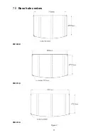
Page 11: ...11 7 0 Base hole centers PM1800B PM2013B PM2415B Figure 2...

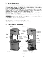
Page 12: ...card carton or packing material until saw is assembled and running satisfactorily 2 Inspect contents Report any shipping damage or part shortages to your distributor 8 3 Spotting the band saw Tools re...

Page 13: ...4 installing rear rail Figure 5 aligning rear rail 8 5 Front rail and guide rail Refer to Figure 6 1 Install front rail to front edge of table using M8x20 button screws HP 1 with M8 lock washers HP 4...

Page 14: ...y loosening hex nut A Figure 11 with 10mm wrench and rotating sliding pad B in or out When fence to table gap is equal retighten hex nut A against fence body Figure 11 fence rear adjustment 8 9 Settin...

Page 15: ...the manufacturer and confirmed by the user as described above you can use the table miter slot to set the fence parallelism 1 Remove the aluminum resaw fence and the lock bar from the fence body and...

Page 16: ...You may either install a UL CSA listed plug suitable for 230 volt operation or hard wire the Band Saw directly to a service panel It is recommended that the three phase Band Saw be connected to a gro...

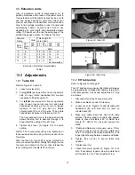
Page 17: ...ody allows the stop bolt to descend through it to keep intact the setting of the 90 stop 4 Tighten lock lever A Figure 20 to secure setting NOTE The circular plate D can be tightened or loosened as de...

Page 18: ...y in the upper and lower blade guides Make sure blade teeth point down toward table and toward the front of the saw If the teeth will not point down no matter how you orient the blade then the blade i...

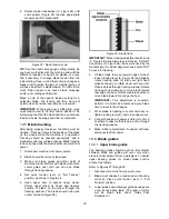
Page 19: ...4 5 Open upper door to expose upper wheel Rotate upper wheel by hand and observe position of blade on the wheel through the tracking window The blade should ride upon center of wheel Figure 26 Figure...

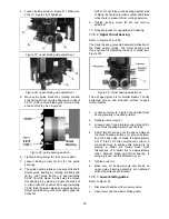
Page 20: ...eat process for opposite guide bearing 10 6 2 Upper thrust bearing Refer to Figures 27 and 30 The thrust bearing prevents backward deflection of the blade during cutting The thrust bearing has three o...

Page 21: ...should be parallel to blade throughout the vertical travel of the guide post thus the guide bearings will maintain their relationship to the blade at any height from the table and won t have to be re...

Page 22: ...top hex nut and adjust screw until it contacts the 90 stop plate 4 Retighten hex nut 5 Loosen set screw at base of pointer B and shift pointer so that it lines up with 90 mark on scale 6 Retighten set...

Page 23: ...ew from lower wheel shaft and remove lower wheel 4 Loosen motor lock handle 5 Raise motor lift handle and retighten motor lock handle to hold motor in raised position 6 Remove old belt and install new...

Page 24: ...start the machine IMPORTANT An interlock switch prevents the band saw from starting if the blade is de tensioned Blade must be tensioned for start switch to activate Likewise if the blade breaks durin...

Page 25: ...ce slowly into the blade while also keeping it pressed against the fence or held against the miter gauge Do not force the workpiece into the blade Some further operating tips Make relief cuts whenever...

Page 26: ...or the following Fence is not parallel to miter slot and blade Blade is not tensioned correctly Blade is dull Teeth have too much set on one side of the blade Workpiece is being fed too quickly Figure...

Page 27: ...e of household ammonia good commercial detergent and 000 steel wool Alternatively commercial rust removers can be found at many hardware stores Apply a light coat of paste wax to the table There are a...

Page 28: ...slowly but more smoothly A coarse pitch fewer teeth per inch will cut faster but more roughly As a rule of thumb the thicker the workpiece the coarser will be the blade pitch If you have to cut a har...

Page 29: ...d to it or carbide tips Because of the importance of blade selection it is recommended that you use the blade selection guide sect 14 0 Also listening to experienced band saw users will produce valuab...

Page 30: ...ally measure the smallest cutting radius required and locate this radius in inches on the chart at the right Follow the curve to where the approximate blade width is specified If a radius falls betwee...

Page 31: ...sary Support bearing s are worn Replace support bearings Surface finish on workpiece is rough Saw blade speed is too low Increase speed Saw blade pitch is too coarse Change to finer pitch blade Saw bl...

Page 32: ...nstructions sect 10 6 2 Blade breaks prematurely Feed force too great Reduce feed force Blade pitch too coarse Refer to blade selection chart use finer pitch blade Support bearing not properly support...

Page 33: ...or starter Building circuit breaker trips or fuse blows Verify that band saw is on a circuit of correct size If circuit size is correct there is probably a loose electrical lead Check amp setting on m...

Page 34: ...too long Replace with adequate size and length cord Low current Contact a qualified electrician 17 0 Replacement Parts Replacement parts are listed on the following pages To order parts or reach our s...

Page 35: ...35 17 1 1 Complete Machine with Accessories PM 1800B 2013B Exploded View I...

Page 36: ...36 17 1 2 Complete Machine with Accessories PM 1800B 2013B Exploded View II...

Page 37: ...37 17 1 3 Complete Machine with Accessories PM2415B Exploded View I...

Page 38: ...38 17 1 4 Complete Machine with Accessories PM2415B Exploded View II...

Page 39: ...1 0 9mm THK 1 15 TS 1490031 Hex Cap Screw M8 x 20 2 16 TS 2361081 Lock Washer M8 7 17 PM1800B 017 Special Flat Washer 2 18 PM1800B 018 Upper Wheel Assembly 1 PM2013B 018 Upper Wheel Assembly 1 PM2415...

Page 40: ...3 Lock Handle M10 1 54 PM1800B 054 Cam 1 55 TS 1490041 Hex Cap Screw M8 x 25 2 56 PM1800B 056 Shaft Fixed Block 1 57 TS 2361101 Lock Washer M10 17 58 TS 1491041 Hex Cap Screw M10 x 30 8 59 PM1800B 059...

Page 41: ...00B 119 Tension Quick Release Handle 2 120 PM1800B 120A Motor 230V 5HP 1Ph 1 PM1800B 120MF Motor Fan not shown 1 PM1800B 120MFC Motor Fan Cover not shown 1 PM1800B 120SC Starting Capacitor not shown 3...

Page 42: ...165 PM1800B 165 Hex Socket Button Head Screw M5 x 35 2 166 PM1800B 166 Plastic Flat Washer 6 x 13 x 1 5t 4 167 TS 1540031 Hex Nut M5 2 168 PM1800B 168 Phillips Pan Head Machine Screw Big M4 x 5 2 169...

Page 43: ...List Index No Part No Description Size Qty 1 PM1800B 018 01 Upper Wheel 1 PM2013B 018 01 Upper Wheel Rubber Coating 1 PM2415B 018 01 Upper Wheel Rubber Coating 1 2 PM1800B 018 02 Spacer 1 3 BB 6306LL...

Page 44: ...1 PM1800B 022 01 Lower Wheel 1 PM2013B 022 01 Lower Wheel Rubber Coating 1 PM2415B 022 01 Lower Wheel Rubber Coating 1 2 PM1800B 018 02 Spacer 1 3 BB 6306LLU Ball Bearing 6306LLU 2 4 PM1800B 018 04 Pl...

Page 45: ...50061 Flat Washer M8 x 18 4 11 TS 2361081 Lock Washer M8 5 12 TS 2248202 Hex Socket Button Head Screw M8 x 20 3 13 PM1800B 027 13 Adjust Plate 1 14 PM1800B 027 14 Block 1 15 5302731 Set Screw M8 x 6 1...

Page 46: ...ge Assembly Parts List Index No Part No Description Size Qty 1 PM1800B 122 01 Brake Arm L 573mm 1 PM2013B 122 01 Brake Arm L 607mm 1 PM2415B 122 01 Brake Arm L 662mm 1 2 TS 1550041 Flat Washer M6 x 13...

Page 47: ...04 Spacer 2 5 PM1800B 059 05 Retaining Ring S15 2 6 PM1800B 059 06 Lower Eccentric Shaft 2 7 PM1800B 059 07 Lower Blade Guide Support Bracket 1 8 PM1800B 059 08 Knob 3 9 TS 1523011 Socket Set Screw M6...

Page 48: ...t 2 7 PM1800B 143 07 Upper Blade Guide Support Bracket 1 8 PM1800B 059 08 Knob 4 9 TS 2276081 Socket Set Screw M6 x 1 x 8 1 10 PM1800B 143 10 Adjustment Shaft 1 11 PM1800B 143 11 Upper Blade Guide Sup...

Page 49: ...runnion Block Front 1 3 PM1800B 124 03 Trunnion Support Bracket 1 4 PM1800B 124 04 Trunnion Block Back 1 5 TS 1523041 Socket Set Screw M6 x 1 x 12 4 6 PM1800B 124 06 Angle Gear Plate 1 7 TS 1515031 So...

Page 50: ...00B 128 07 Gear 1 8 PM1800B 128 08 Fixed Plate 1 9 PM1800B 128 09 Guide Bracket 1 10 PM1800B 128 10 Worm Shaft 1 11 TS 154010 Hex Nut M16 1 12 PM1800B 128 12 Bushing 1 13 TS 1522011 Socket Set Screw M...

Page 51: ...lips Pan Head Machine Screw M8 x 1 25 x 16 1 5 PM1800B 131 05 Worm Shaft 1 6 PM1800B 131 06 Key 4 x 4 x 12 2 7 PM1800B 131 07 Retaining Ring S13 1 8 PM1800B 131 08 Bushing 3 9 TS 1523011 Socket Set Sc...

Page 52: ...d Screw M5 x 0 8 x 20 3 3 TS 1540031 Hex Nut M5 3 4 6295168 Steel Pin 6 2 x 16 1 5 PM1500 109 05 Guide Bar 1 6 6295163 Guide Disc 1 7 PM1800 461 Flat Head Screw M6 x 8 1 8 6295171 Stop Tab 1 9 PM1800...

Page 53: ...6 x 1 x 35 1 8 PM1500 107 16 Spring 1 9 3P12312 Roll Pin 5 x 28 1 10 TS 1541031 Lock Nut M8 x 1 25 1 11 PM1500 107 10 Pad 10 x 28 x 1mm 2 12 TS 1541021 Nylon Lock Hex Nut M6 1 13 PM1800B 150 13 Nylon...

Page 54: ...800B 150 30 Rear Rail for 1800B 2013B L 767mm 1 PM2415B 150 30 Rear Rail for 2415B L 927mm 1 31 TS 2361081 Lock Washer for 1800B 2013B M8 10 TS 2361081 Lock Washer for 2415B M8 11 32 TS 2248162 Socket...

Page 55: ...ITE BLACK GROUND U V S R V U Set at 22A MAGNETIC SWITCH ASSEMBLY LIMIT SWITCH 11 12 24 23 NO C NC RED YELLOW BLACK WHITE WHITE WHITE WHITE BLACK BLACK BLACK BLUE BLUE RED RED BLACK BLACK RED BLACK WHI...

Page 56: ...ASSEMBLY LIMIT SWITCH 11 12 24 23 NO C NC RED YELLOW BLACK WHITE WHITE WHITE WHITE BLACK BLACK BLACK RED GREEN RED BLACK GREEN GREEN RED BLACK BLACK BLACK BLACK WHITE YELLOW RED RED GROUND POWER SUPP...

Page 57: ...ASSEMBLY LIMIT SWITCH 11 12 24 23 NO C NC RED YELLOW BLACK WHITE WHITE WHITE WHITE BLACK BLACK BLACK RED GREEN RED BLACK GREEN GREEN RED BLACK BLACK BLACK BLACK WHITE YELLOW RED RED GROUND POWER SUPP...

Page 58: ...58 This page intentionally left blank...

Page 59: ...59 This page intentionally left blank...

Page 60: ...60 427 New Sanford Road LaVergne Tennessee 37086 Phone 800 274 6848 www powermatic com...

Reviews: