background image


2

Warranty and Service 

WMH Tool Group, Inc., warrants every product it sells. If one of our tools needs service or repair, one of our Authorized Service 

Centers located throughout the United States can give you quick service. In most cases, any of these WMH Tool Group 

Authorized Service Centers can authorize warranty repair, assist you in obtaining parts, or perform routine maintenance and 

major repair on your POWERMATIC

®

 tools. For the name of an Authorized Service Center in your area call 1-800-274-6848. 

MORE INFORMATION 

WMH Tool Group is consistently adding new products to the line. For complete, up-to-date product information, check with your 

local WMH Tool Group distributor, or visit powermatic.com. 

WARRANTY 

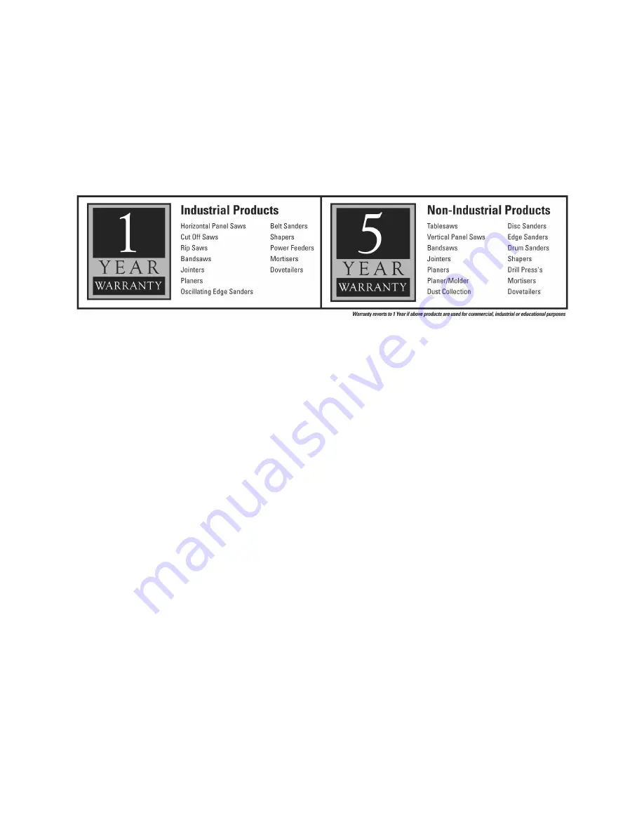
POWERMATIC products carry a limited warranty which varies in duration based upon the product. 


WHAT IS COVERED? 

This warranty covers any defects in workmanship or materials subject to the exceptions stated below. Cutting tools, abrasives 

and other consumables are excluded from warranty coverage. 

WHO IS COVERED? 

This warranty covers only the initial purchaser of the product. 

WHAT IS THE PERIOD OF COVERAGE? 

The general POWERMATIC warranty lasts for the time period specified in the product literature of each product. 

WHAT IS NOT COVERED? 

The Five Year Warranty does not cover products used for commercial, industrial or educational purposes. Products with a Five 

Year Warranty that are used for commercial, industrial or education purposes revert to a One Year Warranty. This warranty does 

not cover defects due directly or indirectly to misuse, abuse, negligence or accidents, normal wear-and-tear, improper repair or 

alterations, or lack of maintenance. 

HOW TO GET SERVICE 

The product or part must be returned for examination, postage prepaid, to a location designated by us. For the name of the 

location nearest you, please call 1-800-274-6848. 
You must provide proof of initial purchase date and an explanation of the complaint must accompany the merchandise. If our 

inspection discloses a defect, we will repair or replace the product, or refund the purchase price, at our option. 
We will return the repaired product or replacement at our expense unless it is determined by us that there is no defect, or that the 

defect resulted from causes not within the scope of our warranty in which case we will, at your direction, dispose of or return the 

product. In the event you choose to have the product returned, you will be responsible for the handling and shipping costs of the 

return. 

HOW STATE LAW APPLIES 

This warranty gives you specific legal rights; you may also have other rights which vary from state to state. 

LIMITATIONS ON THIS WARRANTY 

WMH TOOL GROUP LIMITS ALL IMPLIED WARRANTIES TO THE PERIOD OF THE LIMITED WARRANTY FOR EACH 

PRODUCT. EXCEPT AS STATED HEREIN, ANY IMPLIED WARRANTIES OR MERCHANTABILITY AND FITNESS ARE 

EXCLUDED. SOME STATES DO NOT ALLOW LIMITATIONS ON HOW LONG THE IMPLIED WARRANTY LASTS, SO THE 

ABOVE LIMITATION MAY NOT APPLY TO YOU. 
WMH TOOL GROUP SHALL IN NO EVENT BE LIABLE FOR DEATH, INJURIES TO PERSONS OR PROPERTY, OR FOR 

INCIDENTAL, CONTINGENT, SPECIAL, OR CONSEQUENTIAL DAMAGES ARISING FROM THE USE OF OUR PRODUCTS. 

SOME STATES DO NOT ALLOW THE EXCLUSION OR LIMITATION OF INCIDENTAL OR CONSEQUENTIAL DAMAGES, SO 

THE ABOVE LIMITATION OR EXCLUSION MAY NOT APPLY TO YOU. 
WMH Tool Group sells through distributors only. The specifications in WMH catalogs are given as general information and are 

not binding. Members of WMH Tool Group reserve the right to effect at any time, without prior notice, those alterations to parts, 

fittings, and accessory equipment which they may deem necessary for any reason whatsoever. 

Summary of Contents for 1791291K

Page 1: ...ns and Parts Manual Combination Belt Disc Sander Model 31A WMH TOOL GROUP Inc 2420 Vantage Drive Elgin Illinois 60124 Part No M 0460267 Ph 800 274 6848 Revision G1 6 08 www powermatic com Copyright 2008 WMH Tool Group Inc ...

Page 2: ...or examination postage prepaid to a location designated by us For the name of the location nearest you please call 1 800 274 6848 You must provide proof of initial purchase date and an explanation of the complaint must accompany the merchandise If our inspection discloses a defect we will repair or replace the product or refund the purchase price at our option We will return the repaired product o...

Page 3: ...ectrical Connections 12 Adjustments 14 Platen Adjustment 14 Sanding Table Adjustment 14 Work Stop 15 Belt Arm Positioning 15 Operation 16 Template Forms 16 Fence Table 16 Types of Operations 17 Maintenance 18 Lubrication 18 Extension Cords 13 Guide to Sanding Belts and Discs 19 Troubleshooting 20 Replacement Parts 20 Parts List 31A Sander Body Assembly 21 31A Sander Body Assembly 23 Parts List 31A...

Page 4: ...en contour sanding and swing it back into position immediately after completing the contour sanding task Work area Keep the floor around the machine clean and free of scrap material saw dust oil and other liquids to minimize the danger of tripping or slipping Make certain the work area is well lighted and that a proper exhaust system is used to minimize dust Powermatic recommends the use of anti s...

Page 5: ...Do not use this Powermatic sander for other than its intended use If used for other purposes Powermatic disclaims any real or implied warranty and holds itself harmless for any injury or damage which may result from that use If you are not thoroughly familiar with the operation of sanders obtain advice from your supervisor instructor or other qualified person Drugs alcohol medication Do not operat...

Page 6: ...able Working Height in 34 disc 36 belt 34 disc 36 belt Sanding Arm Locking Positions deg 0 45 and 90 0 45 and 90 Disc Table Size in 17 1 4 x 9 17 1 4 x 9 Disc Table Tilt deg 15 up 45 down 15 up 45 down Belt Table Size in 13 1 4 x 7 1 2 13 1 4 x 7 1 2 Belt Table Tilt deg 45 down 45 down Disc Speed RPM 2375 2375 Belt Speed SFPM 2410 2410 Dust Port Diameter in 4 4 Dust Collection Minimum CFM Required...

Page 7: ...7 Dimensions Figure 1 ...

Page 8: ...and safety instructions Contents of the Shipping Container Container 1 Sander 1 Belt Disc Sander 1 Abrasive Belt 6 x 48 60 grit 1 Abrasive Disc 12 dia 60 grit 1 Disc Table Assembly 1 Fence Assembly 1 Miter Gauge Assembly 1 Bag of Fasteners contains 2 Socket Head Cap Screws M10x25 AA 4 Hex Head Screws M8 x 25 BB 4 Lock Washers M8 CC 4 Flat Washers M8 DD 2 Flat Washers M10 EE 1 Owner s Manual not sh...

Page 9: ...e the sander to the stand with four M8 x 25 hex head screws BB four M8 lock washers CC and four M8 flat washers DD NOTE Hand tighten the screws only until all four are inserted then tighten them completely with a 13mm wrench Refer to Figure 4 5 The drive belt is already mounted on the disc pulley behind the disc as shown in Figure 4 However it should be checked to ensure that it is in the pulley g...

Page 10: ...ur hand while the machine is off The abrasive belt should remain at the center of the drums 7 If the belt veers to one side or the other loosen the locking wheel D and rotate the tracking knob E either left or right until the belt centers itself When manual tracking appears successful turn the machine on for a moment and confirm that the abrasive belt will remain centered during operation If neede...

Page 11: ...sc 2 Remove the backing from the abrasive disc to expose the adhesive and carefully center it on the sander s metal disc Press the abrasive disc firmly working from the center out to prevent creases or air bubbles 3 Tighten the two screws on the front panel When removing an old abrasive disc use mineral spirits or a similar cleaning product to remove any residual adhesive from the sander s metal d...

Page 12: ...is not equipped with a plug You may either install a UL CSA listed plug suitable for 230 or 460 volt operation or hard wire the sander directly to a service panel If the Sander is to be hard wired to a panel make sure a disconnect is available for the operator During hard wiring of the machine make sure the fuses have been removed or the breakers have been tripped in the circuit to which the Sande...

Page 13: ...n of the equipment grounding conductor can result in a risk of electric shock The conductor with insulation having an outer surface that is green with or without yellow stripes is the equipment grounding conductor If repair or replacement of the electric cord or plug is necessary do not connect the equipment grounding conductor to a live terminal Check with a qualified electrician or service perso...

Page 14: ...igure 13 1 Swing the end guard out of position and remove the side cover Remove the abrasive belt 2 Using a 6mm hex wrench loosen the two socket head cap screws inside the belt arm and shift the platen as needed The platen should be 1 32 to 1 16 above the tangent points of the pulleys and in contact with the belt at both ends A straight edge can be used with the abrasive belt to align the platen a...

Page 15: ...If removed for through sanding the work stop should be immediately reinstalled after the through sanding operation unless the fence attachment is used in its place for 45 degree or vertical positions of the arm Use a 10mm hex wrench to remove or install the work stop Belt Arm Positioning Your sander is equipped with an index pin arrangement to lock the belt arm in 0 degree 45 degree and 90 degree ...

Page 16: ...ree angles by loosening the knob A on the center portion of the attachment Manually move the fence to the desired angle and tighten the knob A To position the fence at an angle across the belt for skew sanding as shown in Figure 20 use a 3 16 hex wrench to loosen the two socket head screws B Figure 19 Rotate the fence attachment by sliding it around the bolts using the curved slot C When the desir...

Page 17: ...ence See Figure 23 Edge sanding and flat surface sanding can also be done with the belt arm in a vertical position by using the fence assembly as a table Miters and compound miter cuts can be sanded using the table and the miter gauge Special fixtures can also be designed to use on the table for circular and form sanding Contour sanding can be done using the idler pulley with the end guard swung d...

Page 18: ...closures and there are no loose or worn electrical fittings or wiring If the power cord is worn cut or damaged in any way have it replaced immediately Keep the fence and table surfaces clean and free of rust Lubrication Periodically lubricate the following parts on the 31A Sander Use a good quality non hardening grease on Idler slide Figure 25 table trunnion shown in Figure 9 Use SAE No 10 Oil on ...

Page 19: ...19 Guide to Sanding Belts and Discs ...

Page 20: ...cessive pressure Reduce pressure against belt Abrasive belt slips or stalls on application of pressure Drive belt is loose Properly tension drive belt page 9 Drive belt is loose Properly tension drive belt page 9 Aluminum disc stalls Disc shaft key is missing Replace key Using too much pressure when sanding Reduce pressure against belt Excessive abrasive belt replacement Not using full width of be...

Page 21: ...asting 1 25 31A 25 Rocker Arm 1 26 31A 26 Hex Head Bolt 1 27 31A 27 Platen 1 28 31A 28 Side Cover 1 29 BB 6205ZZ Bearing 6205ZZ 2 30 31A 30 Pan Head Screw w Flange M5 x 8 1 31 31A 31 Bearing Housing 1 32 TS 1551061 Lock Washer M8 3 33 TS 1504051 Socket Head Cap Screw M8 x 25 3 34 31A 32 Key 6 x 6 x 40 1 35 31A 33 Shaft 1 36 31A 34 Special Washer 2 37 31A 35 Pulley 1 38 31A 36 Belt Guard 1 39 31A 3...

Page 22: ...5 4 73 VB A50 V belt A50 1 74 31A 64 Roll Pin 5mm dia x 30 1 75 31A 65 Stop Block 1 76 Sanding Belt local purchase 12 dia 1 77 Sanding Disc local purchase 6 x 48 1 78 31A 68 Lock Knob 8mm x 20 1 79 31A 69 Flat Washer M8 x 30 dia 1 80 31A 70 Lock Knob M10 x 1 25P 1 81 31A 71 Tilting Scale 1 82 31A 72 Rivet 2mm dia x 5 1 83 31A 73 Pan Head Screw M6 x 8 1 84 31A 74 Pointer 1 85 TS 1550041 Flat Washer...

Page 23: ...23 31A Sander Body Assembly ...

Page 24: ... Head Screw M5 x 8 2 19 31A 219 Hex Head Screw M10 x 160 1 20 31A 93 Self Tapping Screw M3 5 x 38 2 21 31A 94 Switch 1PH 1 22 TS 1551061 Lock Washer M8 4 23 31A 223 Hex Head Screw M8 x 20 4 24 31A 95 Hex Head Screw M8 x 25 4 25 TS 1551061 Lock Washer M8 4 26 TS 1550061 Flat Washer M8 12 27 TS 1540061 Hex Nut M8 4 28 31A 97 Motor Cord 1PH 1 29 31A 98 Power Cord 1PH 1 30 31A 99 Hex Nut M10 1 31 31A ...

Page 25: ...25 31A Stand Assembly 1PH ...

Page 26: ...ew M4 x 12 2 16 31A MSA Magnetic Switch Assembly 2HP 3PH 230V 460V 1 31A 16 1 Power Cord 3PH 1 31A 16 2 Motor Cord 3PH 1 31A 16 3 Strain Relief PG25A 16B 2 31A 16 4 Magnetic Switch 1 17 31A 219 Hex Head Screw M10 x 160 1 18 TS 1551061 Lock Washer M8 4 19 31A 223 Hex Head Screw M8 x 20 4 20 31A 95 Hex Head Screw M8 x 25 4 21 TS 1551061 Lock Washer M8 4 22 TS 1550061 Flat Washer M8 12 23 TS 1540061 ...

Page 27: ...27 31A Stand Assembly 3PH ...

Page 28: ...28 Electrical Connections 1 Phase ...

Page 29: ...29 Electrical Connections 3 Phase ...

Page 30: ...30 NOTES ...

Page 31: ...31 ...

Page 32: ...32 WMH Tool Group Inc 2420 Vantage Drive Elgin Illinois 60124 Phone 800 274 6848 www powermatic com www wmhtoolgroup com ...

Reviews: