14
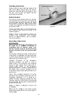
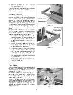
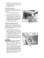
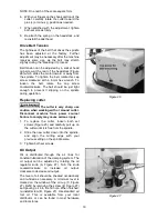
6. Push the headstock back and re-connect
the spring (Figure 13).
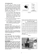
You must now also shift the indication template
(Figure 16). See “Indication Template”.
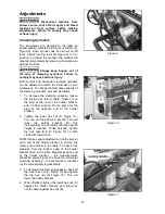
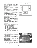
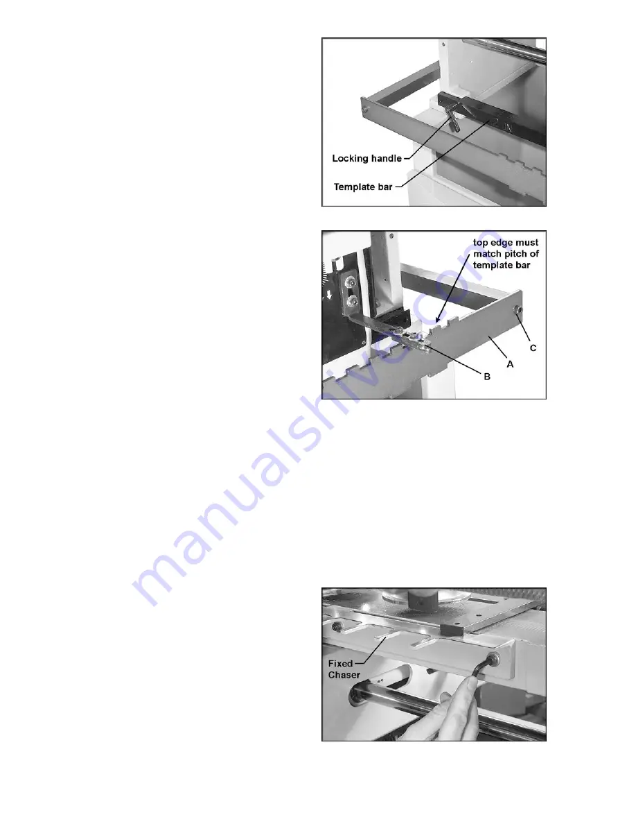
Indication Template
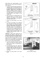
Because the tracer pin is not easily observed
while the machine is in operation, the indication
template (A, Figure 16) provides the operator
with a visual record of the progress of the
“hidden” tracer pin. The bracket (B, Figure 16)
slides in and out of the notches on the indication
template, echoing the tracer pin as it slides in
and out of the notches on the template bar
below.
The pitch of the indication template must match
the pitch of the template bar. Therefore, when
turning the template bar for a new pitch, you
must also change the indication template.
1. First notice how the notches on the
indication template are grouped toward the
right side of the machine. The indication
template should always be oriented in this
fashion.
2. Remove the socket head cap screw (C,
Figure 16) at each end of the indication
template, with a 5mm hex wrench.
3. The indication template that came installed
on your machine contains the 1” and 2”
pitch. The other indication template has the
1-1/2” and 2-1/2” pitch. Either flip the
indication template, or replace it with the
other one as needed, to match the pitch of
the template bar.
4. Re-insert and tighten the socket head cap
screws (C, Figure 16).
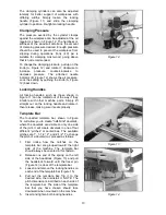
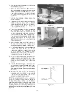
Fixed Chaser
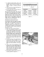
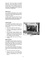
The fixed chaser (Figure 17) provides a support
on which the workpieces rest. The spacing
between the “fingers” of the fixed chaser allows
clearance for the cutter.
The DT65 Dovetailer comes standard with three
fixed chasers at 2”, 2-1/2” and 3” pitches. (Pitch
is the distance between the centers of the
“fingers”; see Figure 18).
NOTE: If you wish to use the 1-1/2” or 2-1/2”
pitch on the template bar, you must replace the
fixed chaser on the machine with one of the
others provided. Figure 18 explains how the
available fixed chasers correspond to the pitch
of the template bar.
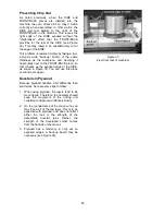
Figure 15
Figure 16
Figure 17
Summary of Contents for 1791305
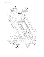
Page 27: ...27 Base Assembly ...
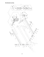
Page 29: ...29 Hold Down Assembly ...
Page 32: ...32 Headstock Assembly ...
Page 34: ...34 Electrical Connections ...
Page 35: ...35 ...
Page 36: ...36 427 New Sanford Road LaVergne Tennessee 37086 Phone 800 274 6848 www powermatic com ...


