19
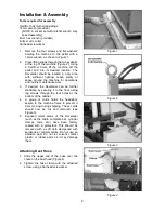
NOTE: One notch of the scale equals 1mm.
6. With your fingers on the shank portion of the
cutter, carefully rotate the cutter toward the
plus (+) or minus (-) position as needed.
7. When satisfied with the adjustment, tighten
both set screws firmly.
8. Re-attach the spring on the headstock, and
re-install the dust hood.
Drive Belt Tension
The tightness of the belt that drives the spindle
has been adjusted at the factory. Further
adjustment may be necessary after the machine
receives some use, as the belt may stretch
slightly during the “breaking in” process.
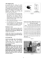
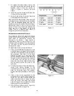
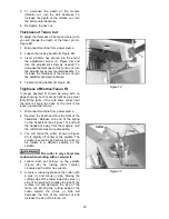
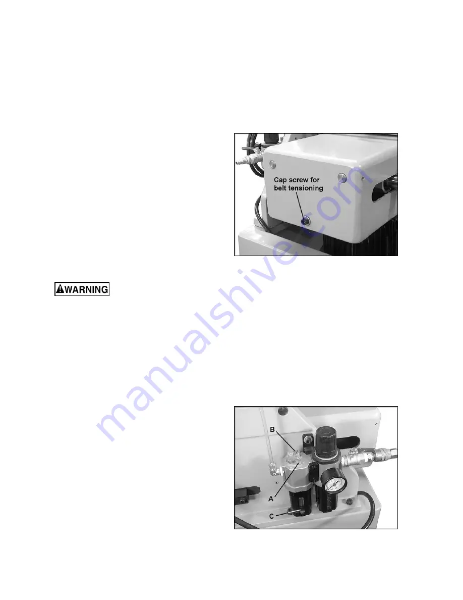
Belt tension can be adjusted by a socket head
cap screw at the rear of the headstock (Figure
26) which slides the motor toward or away from
the spindle. To tighten the belt, rotate this cap
screw clockwise with a 6mm hex wrench. To
loosen the belt, rotate the cap screw
counterclockwise. The belt should be just tight
enough to prevent it slipping on the spindle
during operation.
Replacing cutter
The cutter is very sharp; use
caution when working with or around cutter.
Disconnect machine from power source!
Failure to comply may cause serious injury.
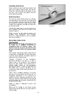
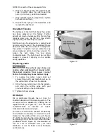
1. To replace the cutter, loosen both set
screws (Figure 25) and carefully pull up on
the cutter until it is free from the spindle.
2. Slide the new cutter down into the spindle,
and align the cutting edge with your
previous setting on the spindle scale.
3. Tighten both set screws.
Oil Output
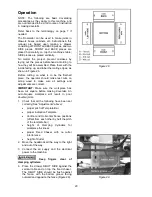
Oil is distributed through the air lines for
constant lubrication of the clamping system. The
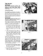
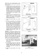
oil output can be adjusted by rotating the oil
regulator knob (A, Figure 27). Turn the knob
counterclockwise to increase oil output,
clockwise to decrease oil output.
The level of oil should be checked occasionally
and re-filled as necessary. A minimum level is
marked on the window of the oil cup (C, Figure
27). Refill by removing the screw (B, Figure 27)
and pouring oil into the fill hole. When finished,
re-install screw (B, Figure 27). Use standard air
tool oil. This is available from your local
distributor, or can be found in most hardware
and tool stores.
Figure 26
Figure 27
Summary of Contents for 1791305
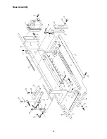
Page 27: ...27 Base Assembly ...
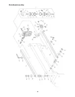
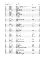
Page 29: ...29 Hold Down Assembly ...
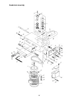
Page 32: ...32 Headstock Assembly ...
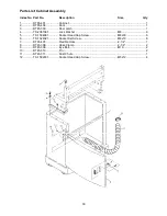
Page 34: ...34 Electrical Connections ...
Page 35: ...35 ...
Page 36: ...36 427 New Sanford Road LaVergne Tennessee 37086 Phone 800 274 6848 www powermatic com ...

