background image


Warnings 

1.  Read and understand the entire owner's manual before attempting assembly or operation. 

2.  Read and understand the warnings posted on the machine and in this manual. Failure to comply with 

all of these warnings may cause serious injury. 

3.  Replace the warning labels if they become obscured or removed. 

4.  This shaper is designed and intended for use by properly trained and experienced personnel only. If 

you are not familiar with the proper and safe operation of a shaper, do not use until proper training 
and knowledge have been obtained. 

5.  Do not use this shaper for other than its intended use. If used for other purposes, Walter Meier  

(Manufacturing) Inc., disclaims any real or implied warranty and holds itself harmless from any injury 
that may result from that use. 

6.  Always wear approved safety glasses/face shields while using this shaper. Everyday eyeglasses only 

have impact resistant lenses; they are not safety glasses. 

7.  Before operating this shaper, remove tie, rings, watches and other jewelry, and roll sleeves up past 

the elbows. Remove all loose clothing and confine long hair. Non-slip footwear or anti-skid floor strips 
are recommended. Do 

not

 wear gloves. 

8.  Wear ear protectors (plugs or muffs) during extended periods of operation. 

9.  Some dust created by power sanding, shaping, grinding, drilling and other construction activities 

contain chemicals known to cause cancer, birth defects or other reproductive harm. Some examples 
of these chemicals are: 


Lead from lead based paint. 


Crystalline silica from bricks, cement and other masonry products. 


Arsenic and chromium from chemically treated lumber. 

10. Your risk of exposure varies, depending on how often you do this type of work. To reduce your 

exposure to these chemicals, work in a well-ventilated area and work with approved safety 
equipment, such as face or dust masks that are specifically designed to filter out microscopic 
particles. 

11.  Do not operate this machine while tired or under the influence of drugs, alcohol or any medication. 

12.  Make certain the machine is properly grounded. 

13.  Make all machine adjustments or maintenance with the machine unplugged from the power source. A 

machine under repair should be RED TAGGED to show it must not be used until maintenance is 
complete. 

14. Remove adjusting keys and wrenches. Form a habit of checking to see that keys and adjusting 

wrenches are removed from the machine before turning it on.  

15. Keep safety guards in place at all times when the machine is in use. If removed for maintenance 

purposes, use extreme caution and replace the guards immediately. 

16. Check damaged parts. Before further use of the machine, a guard or other part that is damaged 

should be carefully checked to determine that it will operate properly and perform its intended 
function. Check for alignment of moving parts, binding of moving parts, breakage of parts, mounting 
and any other conditions that may affect its operation. A guard or other part that is damaged should 
be properly repaired or replaced. 

17.  Provide for adequate space surrounding work area and non-glare, overhead lighting. 

18.  Keep the floor around the machine clean and free of scrap material, oil and grease. 

19.  Keep visitors a safe distance from the work area. Keep children away. 

20.  Make your workshop child proof with padlocks, master switches or by removing safety keys. 

Summary of Contents for 2700

Page 1: ...rts Manual Model PM2700 Shaper Model 2700 WALTER MEIER Manufacturing Inc 427 New Sanford Road LaVergne TN 37086 Part No M 1280100C Ph 800 274 6848 Revision E4 01 2011 www powermatic com Copyright 2011 Walter Meier Manufacturing Inc ...

Page 2: ...mination postage prepaid to a location designated by us For the name of the location nearest you please call 1 800 274 6848 You must provide proof of initial purchase date and an explanation of the complaint must accompany the merchandise If our inspection discloses a defect wewill repair or replace the product or refund the purchase price at our option We will return the repaired product or repla...

Page 3: ...anging Cutter Speed 17 Drive Belt Tension 17 Precision Miter Gauge 18 Handwheel Adjustments 11 Belt Replacement 17 Operating Controls 19 Start Stop 19 Safety Key 19 Digital Readout 19 Operations 20 Special Cuts 29 Troubleshooting for PM2700 Shaper 32 Optional Accessories 33 Parts 33 Ordering Replacement Parts 33 Table Parts List 34 Table Assembly Drawing 35 Fence Parts List 36 Fence Assembly Drawi...

Page 4: ...enic and chromium from chemically treated lumber 10 Your risk of exposure varies depending on how often you do this type of work To reduce your exposure to these chemicals work in a well ventilated area and work with approved safety equipment such as face or dust masks that are specifically designed to filter out microscopic particles 11 Do not operate this machine while tired or under the influen...

Page 5: ...r parts or scrap with the shaper running Avoid awkward operations and hand positions where a sudden slip could cause your hand to contact the cutter 30 Do not attempt to shape boards with loose knots or with nails or other foreign material on its surface Do not attempt to shape twisted warped bowed or in wind stock unless one edge has been jointed for guiding purposes prior to shaping 31 Do not at...

Page 6: ...e correct direction Stock feed Feed stock opposite to the direction of the cutter rotation Figure B Never back stock out of the cutter once the cut has been started Instead pull the stock straight out away from cutter and begin the cut again Guide pin Whenever possible use a guide pin when performing pattern shaping and collar shaping operations Tool maintenance Clean and sharp tools give safer an...

Page 7: ...or 35 1 2 Spindle Size Standard 3 4 1 1 4 Interchangeable Router Bit Collet Size Optional 1 4 1 2 Spindle Capacity Under Nut 3 4 Spindle provided 3 3 4 1 1 4 Spindle provided 6 1 Spindle optional accessory 5 3 4 1 2 Spindle optional accessory 3 1 8 30mm Spindle optional accessory 3 1 2 Spindle Travel 4 Spindle Speeds RPM 7500 10000 reversible Table Opening Diameter 7 33 Insert Opening Diameters 2 ...

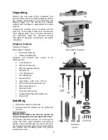
Page 8: ...re and included tools consist of the following items 2 Lock Handle C 2 M13 Flat Washer D 1 Miter Gauge Assembly E 1 Draw Bar F 1 1 1 4 Spindle G 1 3 4 Spindle H 2 Spindle Nut I 3 Insert Rings 2 55 4 16 5 75 J 4 M10 Socket Head Cap Screw K 4 M10 Lock Washer L 1 Starting Pin M 1 8 mm Hex Wrench N 1 Crosspoint Flathead Screwdriver O 1 Wrench P Installing 1 Unbolt the shaper from the skid 2 Carefully ...

Page 9: ... H on two lock handles J Insert the lock handles through slots K on each side of the base Partially thread the lock handles J into two mounting holes L on the table Do not tighten at this time 4 Turn the adjust knob on the bracket to position the fence all the way to the rear 5 Tighten the lock handles J sufficiently to prevent the fence from movement Electrical Connections Electrical connections ...

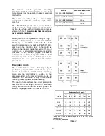
Page 10: ...ancies the diagram in the motor junction box should take precedence Extension Cords The use of extension cords is discouraged Try to position equipment within reach of the power source If an extension cord becomes necessary make sure the cord rating is suitable for the amperage listed on the machine s motor plate An undersize cord will cause a drop in line voltage resulting in loss of power and ov...

Page 11: ...rd H Figure 4 Handwheel Adjustments Referring to Figure 5 The front handwheel B controls the spindle height The side handwheel C controls the casters The Model PM2700 has a retractable caster system that can be extended to permit the shaper to be rolled from one location to another Spindle height 1 Loosen the lock knob B on the spindle height adjust handwheel A 2 Turn the handwheel A clockwise to ...

Page 12: ...rmine which fence is skewed in this example G1 Fig 8 which will require adjustment while the remaining fence G2 will serve as the reference point 6 Remove both fences and place the straight edge against the infeed and outfeed fence castings Figure 9 7 Lock the reference fence D2 and unlock the skewed fence D1 Read step 8 completely before attempting 8 Maintain steady pressure of the straightedge a...

Page 13: ...fence C aside to reveal the limiting setscrew P on the fence casting N 6 Loosen the hex locking nut O with a 10mm wrench and back out the limiting setscrew P with a 3mm hex wrench to permit a sufficient backward and forward adjustment range for the outfeed fence C 7 Slide the outfeed fence C back onto the casting and secure 8 Loosen the outfeed fence lock knob B 9 While maintaining pressure H on t...

Page 14: ...step until the play is removed Note If the gibs are too tight the front handwheel A Fig 3 that controls the spindle height will be difficult to turn 3 When adjustment is complete hold the set screws C in position with the 4mm hex wrench to maintain the setting while tightening the jam nuts B with the 12mm wrench Featherboard Hold downs Referring to Figure 14 The PM2700 Shaper comes equipped with t...

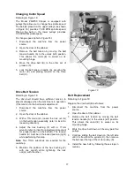
Page 15: ...d until it locks then verify that it will not rotate Installing the Spindle Assembly 3 Thread the nut E onto the threaded end of the spindle D in the direction indicated by arrows A1 A2 Tighten securely by hand 4 Thread the spindle assembly B and nut E onto the arbor C and hand tighten only 5 Insert the draw bar J through the opening in the shaft H just below the drive belt G Turn clockwise fasten...

Page 16: ... secure the shaper cutter A when installation is complete 3 Install the pronged washer E and socket head cap screw F Tighten screw with the 8mm hex wrench provided Unlocking the Spindle 4 Pull out the spindle lock F Fig 15 accessible through the door on the right side of the cabinet Rotate 90º right or left resetting the knob into the indent Using gloves to prevent injury from the shaper cutter tu...

Page 17: ...t the machine from the power source 2 Open the door of the cabinet 3 With a 17mm wrench loosen the lock nut G on the belt tension assembly refer to inset for loosening direction 4 Adjust the hex bushing F with a 17mm wrench refer to inset for adjustment direction for proper tension on the belt B The tension handle A must be in the locked position right while performing this step Note Two 17mm wren...

Page 18: ...removed entirely To adjust loosen two lock handles E position the extension plate and tighten the lock handles To remove slide the extension plate completely off and remove the lock handles E and mounting hardware Calibrating the miter gauge 1 Place the miter gauge in one of the slots H on the table top 2 Set the miter gauge to 90º 0º setting on the scale by loosening the lock handle A then pullin...

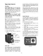
Page 19: ...tch as shown in Figure 20 the magnetic safety key trips a relay which will allow the machine to start and stop when the respective switches are pressed Being magnetic the lock can be removed to make the machine inoperable and can be hidden for safe storage by attaching it underneath the rail or another magnetic surface When using the shaper place the key on the switch cover lining up the arrow on ...

Page 20: ...lace and any other device which insures the safety of the operator Grain Direction Considerations Plan to shape the workpiece in the same direction as the grain when possible Some open grain woods such as redwood fir and oak will leave a rough or slightly splintered edge when cut against the grain Figure 22 Deep cuts require excessive horsepower and pushing force to control the cut Deep cuts can a...

Page 21: ...e shaping operation removes the entire edge of the work e g in jointing or making a full bead the shaped edge will not be supported by the outfeed fence when both fences are in line Figure 26 In this case the stock should be advanced to the position shown in Figure 26 and stopped Turn off the machine and move the outfeed fence forward to contact the workpiece Figure 27 Remove the workpiece start t...

Page 22: ...s determined by the position of the fence relative to the cutterhead and or by the use of shaper collars see Figure 29 Straight Edge Shaping Straight edge shaping is always performed with the workpiece against the fence Use only push sticks and hold downs to keep the workpiece on position Do not use a miter gauge to feed material along the fence face The work piece can bind and cause kickback Fail...

Page 23: ...nd shaping narrow stock it is important that at least one half of the workpiece end be in contact with either the in feed or out feed fence Use a guide similar to the one shown in Figure 31 which tightly clamps the scrap piece to the work piece and provides the necessary width End shaping a narrow work piece without a special guide could result in the workpiece rocking into the cutterhead causing ...

Page 24: ...red edges the operator must first remove the fence assembly In order to control the workpiece and limit the depth of cut the operator must use an anti friction collar with the cutter s as shown in Figure 36 Figure 36 The collar may be positioned above or below the cutter s and its function is to ride against the workpiece or template At the same time the collar will establish the depth of cut as s...

Page 25: ...in always adhere to the following rules for good work and safe operation The collar must have sufficient bearing surface as shown in Figure 40 Also the stock must be fairly heavy in proportion to the cut being made Under no circumstances should a short light workpiece be shaped against the collars as in Figure 41 Note The edge of the work to be shaped must be smooth Any irregularity on the surface...

Page 26: ...n should only be attempted by advanced users If you have never used this method it is recommended you get training from a qualified person Failure to comply may result in serious injury The starting pin is used to support the work when starting the cut 1 The work should be placed in the position 1 Figure 45 using the starting pin as a support 2 Swing the work into the cutter as shown in the positi...

Page 27: ...ed edge except that a starting pin is not required as shown in Figure 48 Note If the whole edge is to be shaped the operator must use a pattern Position the workpiece on the table before starting the motor The operator must do the entire shaping cut by pushing feeding the workpiece into the cutter s Enclosed edge shaping is extremely dangerous The operator must be aware at all times of the directi...

Page 28: ...to secure the template to the workpiece The experienced operator will choose the most appropriate according to the shape size and type construction of the template For example if the workpiece is large enough to extend beyond the front of the table and still leave room for the desired cut it can be securely held to the template with C clamps as shown in Figure 51 In many situations the workpiece i...

Page 29: ...ks the cutters extra care should be taken to see that all parts are clean free of nicks and flaws and perfectly balanced in the stacked position Sash and Door Shaping Shaping a door requires two operations Figure 53 shows the sash cut for the first operation Figure 54 shows the stock flipped over and the sash cutter used with a 1 4 inch groove cutter to complete the cut Figure 55 shows the first s...

Page 30: ...Drop Leaf Bead cutter the table workpiece is shaped with a Drop Leaf Cove cutter With this type joint the whole edge of both workpieces is shaped same side up and allowance made for a 1 16 inch reduction in width Adjust the in feed fence to reduce the workpiece width by 1 16 inch and adjust the out feed fence to compensate for stock removed Taper Cuts Taper cuts can be made by offsetting the fence...

Page 31: ...e ends of legs for tables chairs etc Secure the leg to jig and position for cut as shown in Figure 64 Make all first cuts with the same jig setting and spindle height When the first series of cuts have been made reposition leg on the jig for each succeeding cut Note If the leg is tapered use a wedge to place the side facing the cutter into a 90 degree vertical position as shown in Figure 65 Figure...

Page 32: ... 2 Check for proper rotation at startup 3 Feed work against the cutter rotation 4 Remove cutter and clean with solvent 5 Clean table with solvent Cutter does not come up to full speed 1 Shop wire gauge is too small 2 Extension cord or wiring inadequate size 3 Power source is not adequate 4 Motor not wired for correct voltage 5 Spindle is locked with madrel lever 1 Replace wiring with proper gauge ...

Page 33: ...m throughout pass Use hold downs Make pass slowly and steadily Keep work under cutter whenever possible Cuts not smooth 1 Wrong R P M 2 Feed too fast 3 Working against the grain 4 Cutting too deep on one pass 1 Use faster speed 2 Slow feed speed 3 Work with the grain whenever possible 4 Take several passes on very deep cuts Spindle does not raise freely 1 Shaper dust and dirt in raising mechanism ...

Page 34: ...sembly Index 19 thru 39 1 19 PM2000 323 Miter Gauge Body 1 20 PM2000 324 Pin 1 21 PM2000 325 Miter Gauge Bar 1 22 PM2000 326 Guide Washer 1 23 PM2000 327 Flat Head Machine Screw M6x9 1 24 TS 0050051 Hex Cap Screw 1 4 20x1 2 25 PM2000 329 Socket Head Cap Screw M5x8 2 26 PM2000 330 Support Base 1 27 PM2000 331 Knob 1 28 TS 1521011 Set Screw M4x4 7 29 PM2000 333 Locking Handle 2 30 TS 0810012 Round H...

Page 35: ...35 Table Assembly Drawing ...

Page 36: ...M2700 217 Spring Pin Ø5x32 1 18 TS 2246202 Button Head Socket Screw M6x20 1 19 TS 2361061 Lock Washer M6 1 20 PM2700 220 Fence Body 1 21 PM2700 221 Shaft 2 22 PM2700 222 Lock Knob 2 23 PM2700 223 Washer 2 24 PM2700 224 Left Fence Plate 1 25 PM2700 225 Square Nut M8 2 26 PM2700 226 Right Fence Plate 1 27 TS 1523021 Socket Set Screw M6x8 8 28 PM2700 228 Bushing 2 29 TS 1490051 Hex Cap Screw M8x30 2 ...

Page 37: ...37 Fence Assembly Drawing ...

Page 38: ... 1Ph 1 PM2700 325A Motor 5HP 230V 1Ph 1 PM2700 325B Motor 5HP 230 460V 3Ph 1 PM2700 325CS Centrifugal Switch not shown 1 PM2700 325FC Fan Cover not shown 1 PM2700 325MF Motor Fan not shown 1 PM2700 325SC Starting Capacitor not shown for 3HP 1PH 600MFD 125V 1 PM2700 325RC Running Capacitor not shown for 3HP 1PH 40μF 125V 1 PM2700 325ASC Starting Capacitor not shown for 5HP 1PH 400MFD 250V 1 PM2700 ...

Page 39: ...o Part No Description Size Qty 46 PM2700 346 Hex Bushing 1 47 TS 1540071 Hex Nut M10 1 48 PM2700 348 Belt Tension Handle 1 49 PM2700 349 Spindle Nut Wrench 1 50 PM2700 350 Upper Bushing 1 51 PM2700 351 Wave Washer 1 52 PM2700 352 Lower Bushing 1 ...

Page 40: ...Lock Nut M10 1 25P 1 17 TS 1522011 Socket Set Screw M5x6 4 18 TS 0270021 Socket Set Screw 5 16 18x5 16 5 19 PM2700 519 Fixing Ring 2 20 PM2700 520 Washer M19 2 21 PM2700 521 Woodruff Key 1 22 PM2700 522 Key 5x5x20 1 23 PM2700 523 Shaft 1 24 PM2000 202 Hand Wheel 1 25 PM2700 525 Handle 1 26 PM2700 526 Knob 1 27 PM2700 527 Bracket 1 28 PM2700 528 Tapping Screw M3 1 06Px6 2 29 TS 2361061 Lock Washer ...

Page 41: ...41 Elevator Assembly Drawing ...

Page 42: ...00 611 Lead Shaft 1 12 TS 1550061 Flat Washer M8 2 13 PM2700 613 Elevating Block 4 14 PM2700 614 Caster 4 15 TS 2361081 Lock Washer M8 8 16 TS 1504041 Socket Head Cap Screw M8x20 10 17 PM2700 617 Chain 1 18 PM2700 618 Sprocket Bracket 1 19 PM2700 342 Retaining Ring STW 15 2 20 PM2700 620 Gear 1 21 PM2700 621 Retaining Ring RTW 32 2 22 BB 6002ZZ Ball Bearing 6002ZZ 2 23 TS 1504061 Socket Head Cap S...

Page 43: ...43 Caster Assembly Drawing ...

Page 44: ...pecial Washer 1 14 PM2700 714 Keyed Collar 1 15 PM2700 715 Collar I D 1 x 3 4 T 4 16 PM2700 716 Collar I D 1 x 1 2 T 4 17 PM2700 717 Spindle 1 1 1791205 Spindle Assembly 1 13 thru 17 32 1 1 18 TS 1504051 Socket Head Cap Screw M8x25 1 19 PM2700 719 Special Washer 1 20 PM2700 720 Keyed Collar 1 21 PM2700 721 Collar I D 1 2 x 3 4 T 2 22 PM2700 722 Collar I D 1 2 x 1 2 T 2 23 PM2700 723 Spindle 1 2 1 ...

Page 45: ...45 Spindle Assembly Drawing 1 1 4 Spindle 3 4 Spindle 1 Spindle 1 2 Spindle 30mm Spindle ...

Page 46: ...M2700 425 Junction Box Cover 1 29 PM2700 429 Junction Box 1 30 PM2700 430 Strain Relief 2 31 TS 2311061 Hex Nut M6 4 32 TS 2361061 Lock Washer M6 10 33 PM2700 433 Window 1 34 PM2700 434 Door 1 35 TS 1534042 Phillips Pan Head Machine Screw M6x12 8 36 PM2700 436 Door Latch 1 37 TS 0813022 Slotted Round Head Machine Screw 1 4 20x3 8 2 38 TS 0680021 Flat Washer 1 4 2 39 PM2000 105 POWERMATIC Name Plat...

Page 47: ...8 PM2700 115 Power Cord 3HP 1Ph 14AWGx3C 1 PM2700 115A Power Cord 5HP 1Ph 12AWGx3C 1 PM2700 115B Power Cord 5HP 3Ph 14AWGx4C 1 59 PM2700 159 Cable Connector KST Male Female 3HP 1PH 14AWGx3C 1 PM2700 159A Cable Connector KST Male Female 5HP 1PH 12AWGx3C 1 PM2700 159B Cable Connector KST Male Female 5HP 3PH 14AWGx4C 1 60 PM2700 160 Cable Connector 2000 Male Female 3HP 1PH 18AWGx4C 1 PM2700 160A Cabl...

Page 48: ...48 Cabinet and Base ...

Page 49: ...K LED BLACK WHITE RED YELLOW Electrical Board Magnetic Switch 3HP 230V 1Ph 600MF D 125V AC 40UF 125V AC Motor Black White Green Green Black White Black White White 5HP 230V 1Ph 400M FD 250V AC 35U F 450V AC Electrical Schematic Single Phase V U 5 14 S R 13 V U 5 14 S 6 13 R WHITE BLACK White Black Green Green Green White Black Green Green R ed Red Black White White White Black Green 1 2 3 1 2 3 2 ...

Page 50: ...ack Green Black Black Red White YELLOW WHITE RED BLACK LED BLACK WHITE RED YELLOW Red 5HP 230V 3Ph Electrical Schematic Three Phase Green Red Red V U W 14 L1L2L313 WHITE BLACK Electrical Board Magnetic Switch Green White Green White RED Black Green White Red White Black Red White Red Black Green White X1 Y1 Z1 U1 V1 W1 W2 V2 U2 Black White Green Red ...

Page 51: ... Black Black Red White YELLOW WHITE RED BLACK LED BLACK WHITE RED YELLOW Red 5HP 460V 3Ph Electrical Schematic Three Phase Green Red Red U V W 14 L1L2L313 WHITE BLACK Electrical Board Magnetic Switch Green White Green White RED Black Green White Red White Black Red White Black Yellow Red White Black Red Green W1 V1 U1 U2 X1 V2 W2 Y1 Z1 White Black Red G reen ...

Page 52: ...52 WALTER MEIER Manufacturing Inc 427 New Sanford Road LaVergne TN 37086 Phone 800 274 6848 www powermatic com www waltermeier com ...

Reviews: