8
Unpacking
Remove box and wood crating completely from
around shaper. Check for shipping damage. Report
any damage immediately to your distributor and
shipping agent. Do not discard any shipping
material until the Shaper is assembled and running
properly.
Compare the contents of your container with the
parts lists on this page to make sure all parts are
intact. Missing parts, if any, should be reported to
your distributor. Read the instruction manual
thoroughly for assembly, maintenance and safety
instructions.
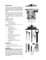
Shipping Contents
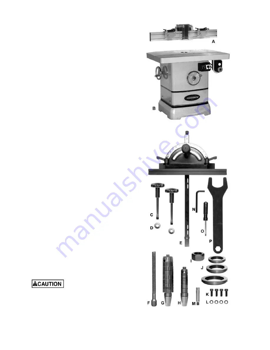
Referring to Figure 1:
Main Shaper Container
1
Fence Assembly (A)
1
Cabinet and Base (B)
Hardware and included tools consist of the
following items:
2
Lock Handle (C)
2
M13 Flat Washer (D)
1
Miter Gauge Assembly (E)
1
Draw Bar (F)
1
1-1/4" Spindle (G)
1
3/4" Spindle (H)
2
Spindle
Nut
(I)
3
Insert Rings – 2.55”, 4.16”, 5.75” (J)
4
M10 Socket Head Cap Screw (K)
4
M10 Lock Washer (L)
1
Starting Pin (M)
1
8 mm Hex Wrench (N)
1
Crosspoint/Flathead Screwdriver (O)
1
Wrench
(P)
Installing
1. Unbolt the shaper from the skid.
2. Carefully slide the shaper from the pallet onto
the floor.
Make sure that the casters do
not get damaged when removing from the skid.
The Shaper should be placed in an area with a
sturdy level floor, good ventilation and sufficient
lighting. Leave enough space around the machine
for mounting extension wings and rail assemblies,
and loading and off-loading stock and general
maintenance work.
Main Shaper Container
Hardware
Figure 1
Summary of Contents for 2700
Page 35: ...35 Table Assembly Drawing ...
Page 37: ...37 Fence Assembly Drawing ...
Page 41: ...41 Elevator Assembly Drawing ...
Page 43: ...43 Caster Assembly Drawing ...
Page 45: ...45 Spindle Assembly Drawing 1 1 4 Spindle 3 4 Spindle 1 Spindle 1 2 Spindle 30mm Spindle ...
Page 48: ...48 Cabinet and Base ...


