9
NOTE: The table can be removed if desired
to make handling the bracket easier,
through this is not necessary for installation.
To remove the table, loosen and remove the
bolt holding table to bracket.
3. Position the rack into the slot in the table
bracket, meshing the rack teeth with the
worm gear.
4. Hold the rack in the slot, while setting the
table bracket over the column. Then slide
table bracket and rack together down the
column.
5. The lower end of the rack should rest in the
lip of the holder, as shown in Figure 6.
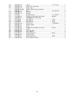
6. Slide the large handle onto the protruding
shaft of the worm (Figure 5), and tighten the
set screw in the handle with a 3mm hex
wrench. Crank the handle counterclockwise
to lower the table bracket down the column.
7. Place the ring onto the column and slide it
down over the top edge of the rack (see
Figure 4). Tighten the set screw on the ring.
8. Screw the locking handle into the table
bracket (Figure 5) and tighten the locking
handle to secure the table bracket’s position
on the column.
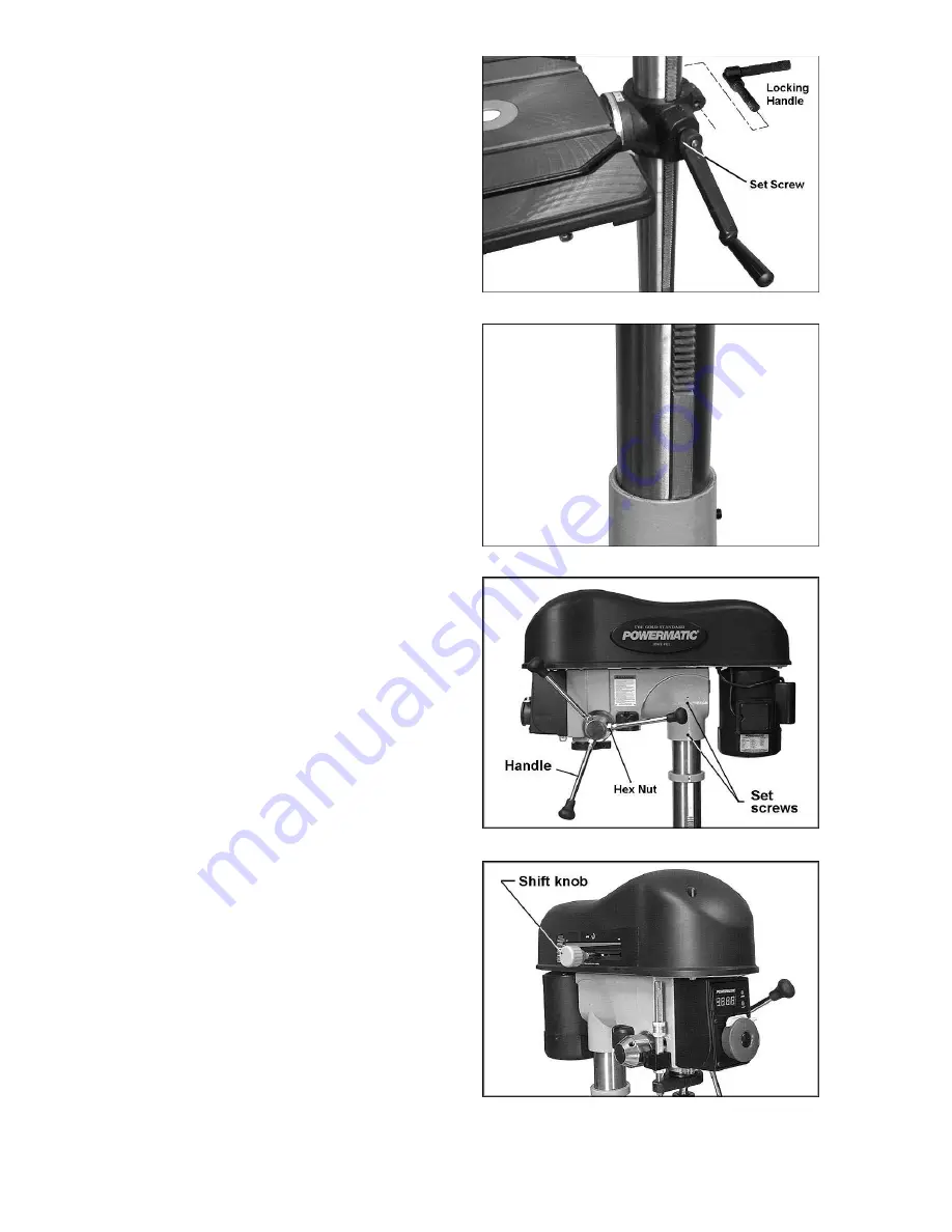
Head Assembly
Referring to Figures 7 and 8:
1. With the help of an assistant, mount the
head assembly to the column, and tighten
the two set screws with a 5mm hex wrench.
See Figure 7.
2. Screw the three downfeed handles into the
threaded holes in the hub. These can be
mounted to either side of the head for your
convenience. Tighten the hex nuts against
the hub.
3. Insert the shift knob into the collar on the
side by screwing it in clockwise (Figure 8).
Figure 5
Figure 6
Figure 7
Figure 8
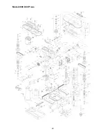
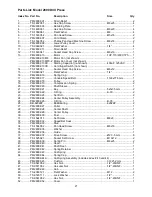
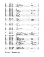
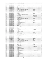
Summary of Contents for 2800
Page 20: ...20 Model 2800 Drill Press ...
Page 25: ...25 Electrical Connections ...
Page 26: ...26 Electrical Connections ...
Page 27: ...27 ...