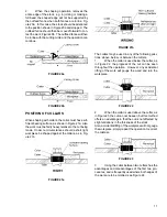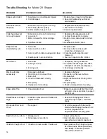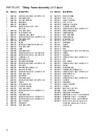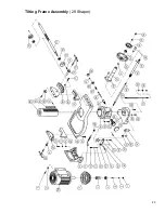
10
Each half of the aluminum fence should be adjusted
as close to the cutterhead as possible without inter-
fering with it. Each can be moved independently de-
pending on the type of work to be done:
4.
Loosen the knob (D) on the connection plate
and slide aluminum fence (E) to position, Figure 16.
Retighten knob (D).
WORK HOLD-DOWNS & SAFETY SHIELD
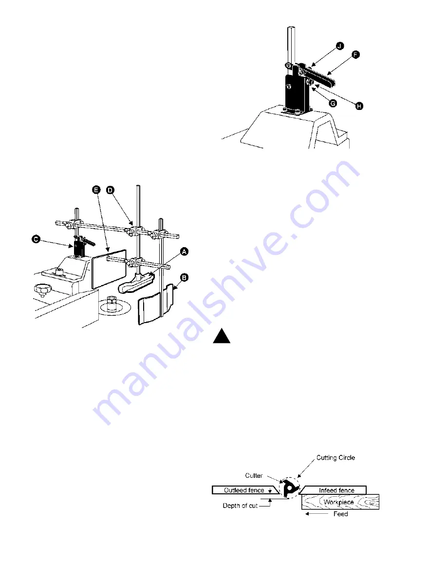
Two hold-downs and one safety shield are included
with the shaper. One hold-down (A) presses stock
down upon the table, the other (B) keeps it pressed
against the fence. These can be mounted to the hold-
down base (C), Figure 17, by the use of wing-nut
blocks (D). The safety shield (E) can be mounted to
either of the hold-down pieces as shown.
FIGURE 17
The hold-down base is factory adjusted to maintain
vertical positioning of the rod. However, if adjustment
is ever necessary, raise the handle (F) and loosen
nut (G) with a wrench. Then turn the socket head
screw (H) with an allen wrench, in or out until the rod
is vertical. See Figure 18. When satisfied, re-tighten
the nut (G). Loosen the soc. hd. screws (J) on the
handle and adjust the eccentric washers behind them
so that the handle can be lowered all the way but still
maintain a degree of tightness. Re-tighten screws.
FIGURE 18
When changing cutters, simply lift handle on hold-
down base (F), Figure 18, and flip entire assembly
back out of the way.
OPERATION
Always release the main spindle from the lock knob
before starting machine (see Figure 10).
Your shaper is equipped with pushbutton magnetic
controls. A start button, power indicator, reversing
switch, and emergency stop are all located on the
front of the machine.
To reverse the rotation of the spindle, simply shut off
the motor and engage the reversing switch.
CAUTION:
NEVER attempt to reverse the ro-
tation of the spindle while the motor is running.
SHAPING WITH THE FENCE
Using the fence is the safest and most satisfactory
method of shaping, and should always be used when
the work permits. Almost all straight work can be
used with the fence.
1.
For normal work, where a portion of the origi-
nal edge of the stock is not touched by the cutter,
both the infeed and outfeed fence are in a straight
line, Figure 19.
FIGURE 19
!
Summary of Contents for 29
Page 1: ...Instruction Manual Parts List M 0460218 800 274 6848 www powermatic com WOOD SHAPER Model 29 ...
Page 17: ...17 Fence Assembly 29 Shaper ...
Page 19: ...19 Spindle Assembly 29 Shaper ...
Page 21: ...21 Shaper Body Mitre Gauge Assemblies 29 Shaper ...


