12
1. Mark your hole centers (2” centers) along
the length of a 2x6. Place the holes so that
the tops of the dowels will be even with the
tops of the ledges on the Lathe. Also, adjust
your hole centers as necessary so that the
first and last dowel will begin at
approximately the same distance from the
ledge at both ends of the Lathe.
2. Use a 5/8” spade bit chucked in a drill press
or in a portable drill. Bore the holes through
one 2x6; this will be the rear piece.
3. On the other 2x6, do not bore through but
only deep enough to securely hold the ends
of the dowel rods. This will be the front
piece and will provide a pleasing
appearance at the front of your Lathe.
4. When all holes have been bored, place the
2x6’s on edge in the outer ledges of the
Lathe.
5. Cut the dowel rods to length with a miter
saw or hand saw, so that after insertion the
rods will be flush with the back of the rear
2x6.
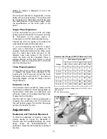
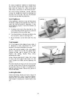
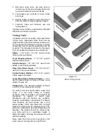
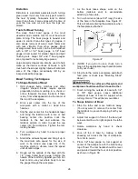
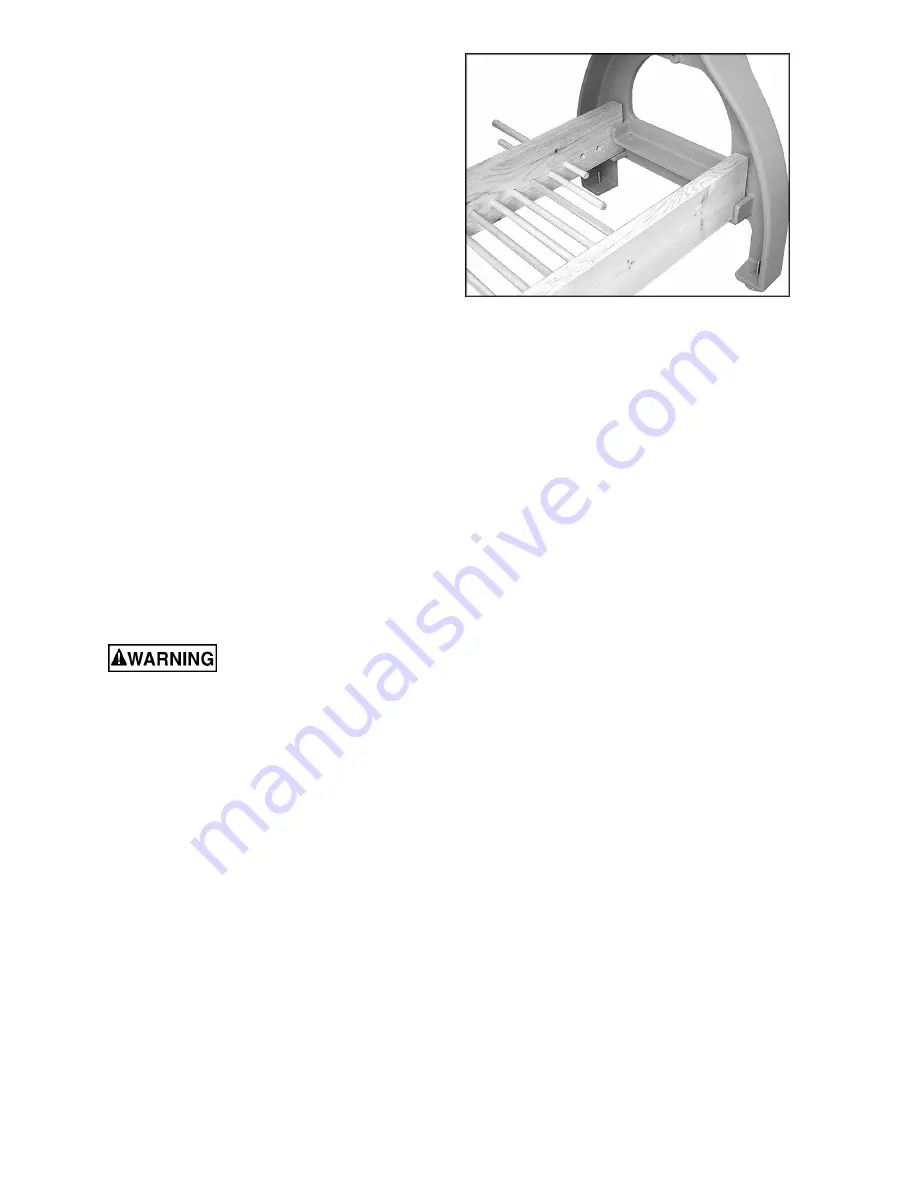
6. Insert the dowel rods through the holes in
the rear 2x6, as shown in Figure 12.
7. A strip of wood can be screwed to the rear
2x6 to cover the dowel holes and prevent
the dowels from working out.
Grounding Instructions
Electrical connections must
be made by a qualified electrician in
compliance with all relevant codes. This
machine must be properly grounded to help
prevent electrical shock and possible fatal
injury.
This machine must be grounded. In the event of
a malfunction or breakdown, grounding provides
a path of least resistance for electric current to
reduce the risk of electric shock.
Improper connection of the equipment-
grounding conductor can result in a risk of
electric shock. The conductor, with insulation
having an outer surface that is green with or
without yellow stripes, is the equipment-
grounding conductor. If repair or replacement of
the electric cord or plug is necessary, do not
connect the equipment-grounding conductor to a
live terminal.
Check with a qualified electrician or service
personnel if the grounding instructions are not
completely understood, or if in doubt as to
whether the tool is properly grounded.
Figure 12
Summary of Contents for 3520B
Page 31: ...31 Headstock Assembly ...
Page 34: ...34 Stand and Bed Assembly ...
Page 40: ...40 Electrical Connections ...
Page 42: ...42 NOTES ...
Page 43: ...43 ...


