17
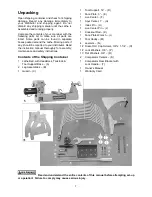
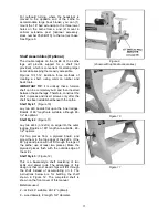
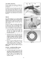
2. Install the comparator spur center into the
headstock bracket, by lifting up on the
spring pin and inserting the comparator spur
center until its point is about even with the
point of the spur center in the headstock
spindle. See Figure 23. The spring pin in the
bracket should engage one of the holes in
the comparator center at this position.
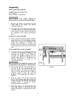
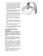
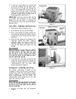
3. Install the rear comparator center in the
tailstock bracket and tighten the bracket
handle. See Figure 24.
4. Mount the spur center with the spindle blank
that you will be turning. Loosen the tailstock
locking handle, and slide the tailstock until
the live center is about 1-inch from the
spindle blank, then tighten the locking
handle. Advance the live center using the
tailstock handwheel, until the live center is
secured in the spindle blank.
5. Mount the reference spindle between the
comparator centers, as shown in Figure 24.
NOTE: The reference spindle should be
mounted last after all adjustment of the
tailstock and ram has been accomplished
with the spindle blank. Likewise, when
turning operation is complete, remove the
reference spindle first.
Speed Change
1. Disconnect Lathe from power source.
2. To change speed ranges, pull open the
access door on the headstock.
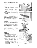
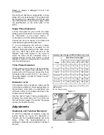
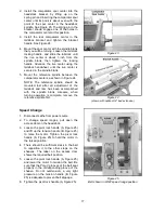
3. Loosen the pivot lock handle (A, Figure 25)
and lift up the tension handle (B, Figure 25)
to raise the motor. Tighten the pivot lock
handle (A, Figure 25) to hold the motor in
the raised position.
4. There should be sufficient slack in the belt
to reposition it to the other steps on the
sheaves. The label on the access door
shows the required belt position.
5. Loosen the pivot lock handle (A, Figure 25)
and lower the motor to tension the belt. Be
sure that the Poly-V grooves of the belt seat
properly in the corresponding groove of the
sheave. Do not overtension; a very light
pressure on the tension handle (B, Figure
25) is adequate to prevent belt slippage.
6. Tighten the pivot lock handle (A, Figure 25).
Figure 23
Figure 24
(shown with optional 18” bed extension)
Figure 25
Belt shown in LOW speed range position
Summary of Contents for 3520B
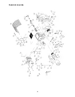
Page 31: ...31 Headstock Assembly ...
Page 34: ...34 Stand and Bed Assembly ...
Page 40: ...40 Electrical Connections ...
Page 42: ...42 NOTES ...
Page 43: ...43 ...

