background image

Summary of Contents for 89

Page 1: ...POWERMATIC OPERATING INSTRUCTIONS AND PARTS LIST Model 89 20 Melal ulling Band Saw Hydraulic Feed For Serial Numbers From 989001 up FEBRUARY 1971 ...

Page 2: ...s adjustments methods of drive 2 MOUNTING Mount machine securely to solid foundation concrete base mounting preferred Locate in clean dry and well ventilated building if possible Motor and electrical connections should be protected when not in operation or if exposed to weather elements 3 INSPECTION The above machine requires a minimum amount of attention in service Periodic or regular inspec tion...

Page 3: ...raulic pump unit and air compressor unit are factory set Do not tamper with safety valves 14 Good housekeeping is one of the most important of all safety rules DESCRIPTION The Model 89 Band Saw is a 20 medium duty variable speed metal and wood cutting saw with an integral hydraulic feed mechanism The frame is constructed of welded steel plate for rigidity The bandwheels have crowned rubber tires d...

Page 4: ...NDWHEEL TRA NSMISSION SURGE TA NK PAGE 4 COOLANT TAN GUIDE BAR LOCK GU IDE BAR TRUN ION TILT TRAVELING SCALE INSERT TABLE LOCK FLOW rO NTROL VALVE MOTOR 4 WHEEL TILT KNOB t _ l _ I3LADE TENSION SPEED E MANUAU HANDWHEEL HYDRAULIC PUMP HYDRAULIC RESERVO IR POWERMATIC HOUDAILLE McMinnville Tennessee ...

Page 5: ...ty Blade length Type blade Blade speed Table size Table Tilt Power feed stroke Power feed force Power feed speed Saw Motor Hydraulic Motor Hydraulic Pump Weight POWERMATICj HOUDAILLE McMinnville Tennessee 19V2 12 Va to 149 to 151 Carbon Steel 40 4600 SFM 24 x 24 8 250 lbs 0 36 IPM 2 HP Va HP 1 5 GPM 100 PSI 1 135 lbs ao DIMENSIONAL DRAWING 89 BANDSAW 0140012 PAGE 5 ...

Page 6: ... tracking steadily and in the center of the wheels The back of the blade should barely touch the bearing in the upper and lower guides The sides of the blade should barely clear the guide inserts and have approximately the same clearance on each side Complete all blade adjust ments to upper and lower guide assemblies before re installing the power cylinder assembly PAGE 6 BLADE TENSION Correct bla...

Page 7: ...d pour out oil Loosen set screw 6716004 and remove clutch shift shaft 3704007 and clutch shift fork 3216004 Remove bearing cap 3078005 and bearing cap gasket 3234231 Remove cap screws 6714014 and remove variable speed arm bracket 3064079 Put sliding clutch in neutral position and with screwdriver or punch remove wheel shaft lock ring 6670037 Lock ring is located between clutch 3095003 and high spe...

Page 8: ...lter is connected to the pump suction line inside the tank The filter will remove most of the impuri ties and abrasive particles from the system but in order to maintain long life for the hydraulic com ponents the oil must be changed periodically per the lubrication schedule The directional control valve is used to control the direction of the table insert movement It has three positions down for ...

Page 9: ... 1 and the insert 3 will begin to travel Increase the feed rate slowly until the desired feed is obtained Excessive feed will result in chattering or broken saw teeth When workpiece has been cut pull directional control handle up and the insert will retract Always keep the directional control valve in neutral when the saw is not being used If the operator turns on the pump when the directional con...

Page 10: ...workpiece in the guide CHIPBLOWER COOLANT The mist coolant assembly is comprised of a coolant tank 1 air valve 2 coolant valve 3 mixing nozzle 4 and air compressor When applied to the point of work it increases saw life gives a finer finish and increases the speed of cut ting The mist should be directed onto the cutting edge of the saw band this will assure coolant flowing on both sides of the saw...

Page 11: ...nd fed by hand To adjust the fence loosen the knobs 1 and move the fence 2 along the bar 3 to the desired location CAUTION Use appropriate Push Stick to keep hands away from the moving blade BAND FILE The band file attachment provides a means of power filing File bands are available in different widths and shapes To mount the attachment it is necessary to remove the power insert assembly the fixed...

Page 12: ...e 8 Incorrect choice of saw band 9 Incorrect saw band tension SAW BAND TEETH STRIPPING Usually caused by chip welding 1 Saw band pitch too coarse for thin work section 2 Work not held firmly to stop vibration 3 Feed too fast 4 Band speed too low PREMATURE SAW BAND BREAKAGE Usually caused by teeth stripping 1 Saw band speed too low 2 Feeding speed too high 3 Pitch of saw band too coarse Use finer p...

Page 13: ...ly Table Tilt Lock Gears Lubriplate 630 AA Grease Lightly 6 Monthly Post Wipe Oil on Post and SAE 20 Oil Work into Block 7 Monthly Band Tension Screw Thrust Lubriplate 630 AA Bearing Grease 8 Monthly Band Tension Screw SAE 20 Oil Oil Lightly 9 Monthly Upper Wheel Slide Grease Lubriplate 630 AA 10 Butt Welder See Separate Manual for Complete Lubrication Instructions 11 Monthly Hydraulic Reservoir M...

Page 14: ...n ______________________ Gasket Bearing Cap _____________________ Housing Transmission ____________________ Key 3 16 x 3 16 x 1 19 ___ _________ 1 1 2 1 1 1 2 1 3 1 1 1 2 1 1 4 1 1 Part Number 3388020 3585214 3589004 3700015 3704007 3706016 3717019 3741007 3741008 3745001 3758006 3758203 3800010 6060016 6060062 6063001 6063002 6063004 6063005 6080021 6420002 6420003 6452003 6605006 6634029 6638004...

Page 15: ...lex loc Thin Ht 9 16 18 __ 1 Pin Spring 3 16 x 1Va 19 ____________ 3 Pin Spring 3 16 x 8 19 ________________ 2 Screw Soc Set Cup Pt 10 24 x 3 16 19 ______________ POWERMATIC HOUDAillE McMinnville Tennessee Part Number 6714004 6715016 6715035 6747000 6813030 6861200 6861702 6861901 Part Name Quantity Required Screw Soc Set Cup Pt 1iI 20 x 1A 19 ______________________ Screw Soc Set Cup Pt 5 16 18 x ...

Page 16: ..._____ _________ Bar Balance Weight ________________________ Part Number 3058011 3063041 3063078 3083017 3094011 3244035 3254008 3271008 3289023 3298034 3388020 3406017 3406018 3481006 3582028 3604004 3684210 3684212 3690028 3690029 3695021 3700014 3850002 6060014 6064000 6339001 6506003 6515001 6516009 6518008 6706037 6706038 6710065 6714004 6714018 6714049 6714082 6747000 6715016 6715039 6716007 ...

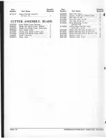
Page 17: ...____________ Nut Hex 6 32 __________________________ Pin 0 oweI 14 x 1 19 ____________________ Pin Dowel 3 16 x 1 Lg ____________ Pin Dowel x 1 Lg ____________________ 1 1 1 1 1 1 1 3 1 2 1 POWERMATIC HOUDAILLE McMinnville Tennessee Part Number 6626002 6706027 6708001 6861101 Part Name Quantity Required Pin Spring x Lg ___________________ 1 Screw Fil Hd 6 32 x Lg ___ 3 Screw Soc Set 8 32 x 3 16 19...

Page 18: ...____________________ _____ ____ _ 2 Part Number 3670030 3735014 6514001 6514002 6515001 6670005 6710060 6714048 6714051 6715034 6861100 6861200 Part Name Quantity Required Rod Cam Oper _____________________ _____ 1 Spacer Inside B S Blade Cutter ___ 2 Nut Hex 20 _____________________ 2 Nut Hex Lock 20 _____________ 1 Nut Hex 5 16 18 ____ _______________ ___ 3 Ring Retaining Tru Arc 51 00 100 _____...

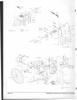
Page 19: ...69 0460072 6714127 fC 3078005 6716003 1 3388020 3234231 31 00015 6060016 o 1 33BB 008 f 64S 60 6063004 _ m 6716003 _ I W 606 6715013 375B006 3001 6063001 h5003 2753005 r3083001 A __ e eee 63002 _____2850003 3 6063002 2095002 ___ _ 3083001 QJ l Sc 3 1 6638004 ff It 2 6714127 3078004 3741007 3704007 POWERMATICj HOUDAI LLE McMinnville T ennessee PAGE 19 ...

Page 20: ...I I 3063017 3690029 7033 6716061 2 6516009 2 3064061 2705002 LCMlER COUNTERSHAFT As5Y 670603B 6860600 7OO014 I 3386020 I 3650002 3406016J I 3044042 PAGE 20 714004 1I 3461006 5039 901 30940 fA 6661301 714049 t I t se13029 6714016 32 4006 3481006 I 3461006 I 6661100 6714049 t06307B I J 6715016 L327100B 2250049 6714082 UPP R WHEEL HOUSING A55Y 0460071 POWERMATIC HOUDAILLE McMinnville Tennessee ...

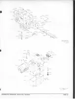
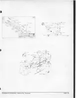
Page 21: ...4024 ft 6620001 IA 3 6861901 3701042 ooc OO v k ro 7 6126 1568009 __ 6621001 6626034 336400 692001 tr 6620001 3055024 3529002 Q Q oro Lff ro 3025024 REF 306407 0 6518oo8 I 67I O07 I 2602007 279801 3816049 Bf 816047 ft 61300 65l6007 1Qp Bo NDSAW MA A TTl Irc HOUDAILLE POWER I Tennessee McMinnvi Ie BANO SAW MOD 87 E ECTOR ASSY SPEED SBWH 7 17 69 269BOOI MPING UNiTtTANK 89 HYD PUASS Y 60073 DWG BY JM...

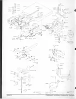
Page 22: ...6715015 3583001 FENCE RIP A5Sv 2195001 J 6716119 Q S REFlUPPER GUIDE BAR 6715C15 b 3044014 6861301 6710017 6861300 a ilt 3583001 l 1J 3289005 13253026 3253027 3253028 6B61201 6861200 J 6715034 BAND FILING ATTACHMENT BwH 7 18 69 202800 I PAGE 22 3673029 n I 3055052 A 3583026 6623038 u U 6715016 3708004 3673029 MODEL B9 BAND SI iII HYDRAULIC TABlE ASS Y aBYARS IS JUlY 69 0460074 1 6765010 GUIDE MATE...

Page 23: ...71 l48____ 7 4051 CUTTER ASSY BlADE 3406201 POWERMATIC HOUDAILLE McMinnville Tennessee 6626032 2406004 o 6715106 3289006 3604007 6715034 3064056 CtR LE CUTIING ATTACH 2028001 PAGE 23 ...

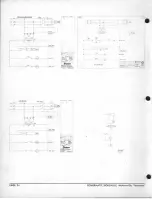
Page 24: ...z v Y oo d L b Y x 115 1 xz PUMP MOTOR HP 10 115 1 _o o 0 o e GRINOE R 0 o WORK LIGHT PAGE 24 j 1 ov __ 30 o l O r_ r_ T KVA IPS 21 8 STOP IOl 0 N N j j C _ C 30 MAGNETICS ISAW START PUMP t AOT QR V3 HP 0 11 5 1 W OR K LIGHT HI SO M IoTlC SANDSotoW 0940040 l_WELDER t15A POWERMATIC HOUDAILLE McMinnville Tennessee ...

Reviews: