12
Note:
You may need to re-adjust clamping
pressure (described below) after aligning fence.
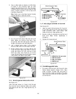
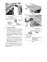
Figure 6-16
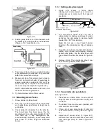
Figur
e
6-17
6.6.3
Clamping pressure adjustment
The Accu-Fence has been pre-set by the
manufacturer to lock securely when handle is
pushed down. If adjustment is needed:
1. Unlock fence and remove it from guide rail.
2. Adjust each of two setscrews (C, Figure 6-17)
exactly the same number of rotations until
fence is held securely when handle is pushed
down.
Clockwise rotation of setscrews will increase cam
pressure. Counterclockwise rotation will decrease
cam pressure.
6.6.4
90
to table adjustment
1. Place fence on saw table and lock it.
2. Place a square (D, Figure 6-16) on table next
to fence. Fence should be 90
to table.
3. If adjustment is necessary, unlock fence, and
turn one of two nylon adjustment screws (E,
Figure 6-16) until fence is 90
to table.
4. Lock fence and verify the adjustment.
6.6.5
Cursor adjustment
1. Disconnect table saw from power source.
2. Remove blade guard and raise blade above
tabletop.
3. Unlock fence and slide it to approximately 4-
inches from saw blade. Lock fence.
4. Measure distance between saw blade and
inside of fence.
Note:
Measure from a tooth
edge, not the flat side of the blade.
5. Adjust cursor (F, Figure 6-16) to read the
distance just measured, and tighten cursor
assembly to fence.
6. Take a test cut and confirm that the
adjustment is correct.
Note: Slots in cursor should allow enough
adjustment travel. If cursor lacks enough travel to
give correct measurement, loosen guide tube and
adjust as needed. If you still cannot achieve correct
measurement, loosen front rail and adjust as
needed. If you have to adjust front rail, you will
need to go through front rail assembly instructions
again.
Cursor position should be checked after installing a
new blade.
6.7
Side plate replacement
The Accu-Fence is specially designed to save
many hours of down-time when side plates need to
be replaced. In an operation that can last an entire
day with other fences, the Accu-Fence side
replacement takes only a few minutes.
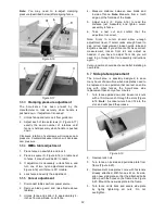
1. Turn fence upside down and loosen lock nuts
with a 10mm wrench through the slots (Figure
6-19.
Note:
A socket wrench can fit into the
slot, and will speed the process.
Figure 6-19
2. Remove lock nuts.
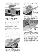
3. Turn fence on its side and pull side plate from
frame (Figure 6-20).
4. Replacement side plates come with fasteners
already attached. With fence still on its side,
align new side plate so that the attached bolts
line up with the holes on the frame. See Figure
6-20. Mount the new side plate to the frame.
5. Turn fence on its back and secure side plate
by lightly tightening all nuts. Do not
overtighten.


