background image


Assembly 

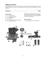
Refer to Figure 1. 

1. Insert the 

handwheel assembly 

(F) into the 

clamp bracket

 (B) and secure with the 

lock 

handle 

(A) on the clamp bracket. 

2. 

Attach the 

clamp bracket

 (B) to the back of 

the fence (G) using two M10 x 25 

socket head 

cap screws

 (D) and M10 

lock washers

 (E

). 

3. 

Attach the handles (C) to the clamp 
bracket

 (B). 

Note: 

There are two slots on the underside of the 

tenoning jig. For the JTSA-10XL, 66 and 64A JET 
& Powermatic left tilt saws, mount the slide (H) 
into the left slot (farthest from the fence). A 4 mm 
hex wrench (provided) is required. 


Alignment


Disconnect saw from power 

source before making adjustments to the 
tenoning jig. 

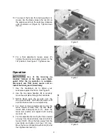
To align the tenoning jig: 

1.  Place the jig guide into the saw's left miter 

gauge slot. 

2.  Using a square (A, Fig. 2), check to see if the 

fence is 90 degrees to the saw table.  To 
make an adjustment to the fence, loosen the 
lock handle (B), adjust the fence to the 
90-degree position and tighten lock handle. 

3.  When the fence is 90 degrees to the table, 

tighten setscrew (C) until it bottoms.  See 
Figure 2.  Setscrew (C) acts as a positive stop 
and allows you to quickly position the fence 
back to the 90-degree position after it has 
been tilted. 


Figure 1 


Figure 2 


Summary of Contents for JTG-10Q

Page 1: ...s and Parts Manual Tenoning Jig Model JTG 10Q WMH TOOL GROUP 2420 Vantage Drive Elgin Illinois 60123 Part No M 708295 Ph 800 274 6848 Revision A 10 04 www wmhtoolgroup com Copyright WMH Tool Group This Manual is Bookmarked ...

Page 2: ...o misuse abuse negligence or accidents normal wear and tear repair or alterations outside our facilities or to a lack of maintenance WMH TOOL GROUP LIMITS ALL IMPLIED WARRANTIES TO THE PERIOD SPECIFIED ABOVE FROM THE DATE THE PRODUCT WAS PURCHASED AT RETAIL EXCEPT AS STATED HEREIN ANY IMPLIED WARRANTIES OR MERCHANTIBILITY AND FITNESS ARE EXCLUDED SOME STATES DO NOT ALLOW LIMITATIONS ON HOW LONG TH...

Page 3: ...s 10 Parts 10 Replacement Parts 10 Parts List 11 Exploded View 12 The specifications in this manual are given as general information and are not binding WMH Tool Group reserves the right to effect at any time and without prior notice changes or alterations to parts fittings and accessory equipment deemed necessary for any reason whatsoever ...

Page 4: ...om chemically treated lumber 9 Your risk of exposure varies depending on how often you do this type of work To reduce your exposure to these chemicals work in a well ventilated area and work with approved safety equipment such as face or dust masks that are specifically designed to filter out microscopic particles 10 Do not operate this jig while tired or under the influence of drugs alcohol or an...

Page 5: ...r cutters sharp and clean for the best and safest performance Follow instructions for lubricating and changing accessories 27 Make sure the work piece is securely attached or clamped to the jig Never use your hand to hold the work piece 28 Turn off the machine before cleaning Use a brush or compressed air to remove chips or debris do not use your hands 29 Do not stand on the machine Serious injury...

Page 6: ...ions Model Number JTG 10Q Stock Number 708295 Box Contents A 1 ea Fence assembly B 1 ea Handwheel Assembly C 1 ea Clamp bracket D 2 ea Handles E 2 ea Socket Head Cap Screws M10x25 F 1 ea Lock washers M10 Note Exposed metal parts have been given a protective coating at the factory This should be removed with a solvent such as mineral spirits Do not use an abrasive pad Required Tools G 1 set hex wre...

Page 7: ...rom the fence A 4 mm hex wrench provided is required Alignment Disconnect saw from power source before making adjustments to the tenoning jig To align the tenoning jig 1 Place the jig guide into the saw s left miter gauge slot 2 Using a square A Fig 2 check to see if the fence is 90 degrees to the saw table To make an adjustment to the fence loosen the lock handle B adjust the fence to the 90 degr...

Page 8: ...cking handle G and thumb screw H 7 To bring the fence into parallel with the saw blade loosen both locking handles G L See Figure 4 Reposition the jig so that the fence lies flat against the saw blade and tighten both locking handles 8 The miter bar slots in the base are milled to be parallel to the fence If an adjustment is necessary loosen the two hex socket head screws A holding the guide rod t...

Page 9: ...wheel A to tighten your workpiece against the fence See Figure 8 2 Use the two large handles B to securely move the workpiece through the saw blade 3 NOTE Never pass the jig back over the moving saw blade Wait until the power is off and the blade comes to a complete stop 4 For rapid or large adjustments moving the fence toward or away from the saw blade loosen both locking levers C D Move the fenc...

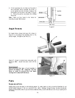
Page 10: ...e tighten lock lever F Figure 11 shows an angle tenon procedure with the fence tilted Loosen lock lever H to tilt the fence This type of cut requires a spacer J between the workpiece and the fence in order to prevent the saw blade coming into contact with the fence Figure 9 Figure 10 Figure 11 Parts Replacement Parts Replacement parts are listed on the following pages To order parts or reach our s...

Page 11: ... 26 1 JTG10 26 1 Guide Washer 1 26 2 TS 081F021 Flat Head Machine Screw 1 4 20 x 3 8 1 27 JTG10 27 Set Screw M8x50 1 28 TS 0680041 Flat Washer 3 8 2 29 TS 1540061 Hex Nut M8 1 30 JTG10 30 Locking Handle M8 1 31 TS 2284082 Pan Head Machine Screw M4x8 1 32 JTG10 32 Pointer 1 33 JTG10 33A Fence 1 34 JTG10 8 Socket Set Screw M6x40 1 35 JTG10 35 Stop 1 37 JTG10 37 Stud 1 38 TS 1523071 Socket Set Screw ...

Page 12: ...12 Exploded View ...
Reviews: